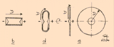
Take a look at figure d below, from here Electro-acoustic models
It appears to be possible, using a torus-like baffle, to spread the interference nulls in space and time, so does something similar to this diagram actually become a viable option?
It appears to be possible, using a torus-like baffle, to spread the interference nulls in space and time, so does something similar to this diagram actually become a viable option?
Attachments
I think you should, for your own sake, explain your idea in a little more detail. Please do. I don't want to put words in your mouth about what you are thinking here, exactly.
What you are showing is just a "thought experiment" showing how a tube can be squashed into an equivalent planar, circular baffle, and how the front-to-back distances compare.
What you are showing is just a "thought experiment" showing how a tube can be squashed into an equivalent planar, circular baffle, and how the front-to-back distances compare.
"For my own sake"? ") Sure, it's a combination of ideas. According to Earl Geddes a torus mitigates edge diffraction https://www.diyaudio.com/forums/mul...od-diffraction-baffle-edge-2.html#post4819063
Sure, it's a combination of ideas. According to Earl Geddes a torus mitigates edge diffraction https://www.diyaudio.com/forums/mul...od-diffraction-baffle-edge-2.html#post4819063
Sure, it's a combination of ideas. According to Earl Geddes a torus mitigates edge diffraction https://www.diyaudio.com/forums/mul...od-diffraction-baffle-edge-2.html#post4819063Ah, I see what you are talking about. Take a "donut" torus. Install a baffle inside of the hole in the middle, then install a driver in that. Is that correct? Like this:
Earl Geddes, from what I recall, is opposted to open baffle speakers because he feels they have "twice the diffraction" of a regular speaker: diffraction off of the baffle edge once from the front radiation, and diffraction off of the baffle edge once from the rear radiation. I find that argument rather academic and specious.
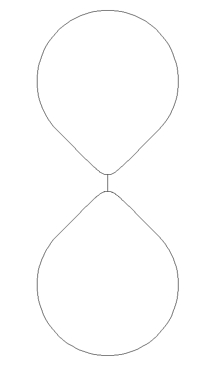
Firstly, diffraction is not what gives rise to oscillations in the on or off axis response from a dipole. In a boxed loudspeaker that IS what is causing the oscillations at the top of and above the baffle step, and the more regular the distance to the edge the worse these will be. In a dipole speaker it is front-to-back pathlength differences that give rise to cancellation or addition of the front and rear waves, and these result in the oscillations. Using a toroidal baffle shape will not change that. Also, the old two-monopole-source model of a dipole has shown to be INVALID at and above the dipole peak. From the page on SL's web site that you linked to just look at the difference between the two figures, below. The first is the two-monopole model, and the second is a more complete simulation that I find matches actual driver measurements very well. These are not at all the same at and above the dipole peak regarding the "oscillations" in the responses.
Regarding the diffraction of the edge being problematic, the diffraction is opposite in polarity from front and rear, and I would like to think that there is quite a lot of, if not complete, cancellation. This would be more true at low frequencies than higher ones I suppose. I also feel that the sonic influence of diffraction, just like jitter in digital music, is so over blown and concerns are so over-hyped that it is laughable. So maybe I am a little jaded about the whole thing.
Earl Geddes, from what I recall, is opposted to open baffle speakers because he feels they have "twice the diffraction" of a regular speaker: diffraction off of the baffle edge once from the front radiation, and diffraction off of the baffle edge once from the rear radiation. I find that argument rather academic and specious.
Firstly, diffraction is not what gives rise to oscillations in the on or off axis response from a dipole. In a boxed loudspeaker that IS what is causing the oscillations at the top of and above the baffle step, and the more regular the distance to the edge the worse these will be. In a dipole speaker it is front-to-back pathlength differences that give rise to cancellation or addition of the front and rear waves, and these result in the oscillations. Using a toroidal baffle shape will not change that. Also, the old two-monopole-source model of a dipole has shown to be INVALID at and above the dipole peak. From the page on SL's web site that you linked to just look at the difference between the two figures, below. The first is the two-monopole model, and the second is a more complete simulation that I find matches actual driver measurements very well. These are not at all the same at and above the dipole peak regarding the "oscillations" in the responses.
Regarding the diffraction of the edge being problematic, the diffraction is opposite in polarity from front and rear, and I would like to think that there is quite a lot of, if not complete, cancellation. This would be more true at low frequencies than higher ones I suppose. I also feel that the sonic influence of diffraction, just like jitter in digital music, is so over blown and concerns are so over-hyped that it is laughable. So maybe I am a little jaded about the whole thing.
Do you know what's going on here, Allen's sim appears to be showing no on axis nulls? https://www.diyaudio.com/forums/multi-way/361169-polar-response-frame-ob-speakers-6.html#post6370340
Do you know what's going on here, Allen's sim appears to be showing no on axis nulls? https://www.diyaudio.com/forums/multi-way/361169-polar-response-frame-ob-speakers-6.html#post6370340
If I use a driver, without baffle (nude), it doesn't have any on axis nulls either. You can easily confirm this with the Edge when the driver radiating surface and baffle edge are close together. If diffraction is a problem, why would it not be worst in this case with a circular, sharp edge?
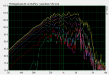
Using, for example, a nude 15" driver I only measure very smooth responses all the way up until the cone breakup region. Here is a measurement with better than 50Hz resolution to prove it:
If the torus shape seems to be worth pursuing then someone should definitely build it, possibly in a couple of difference sizes, and perform some high resolution (e.g. outdoor) measurements that will show what is going on in more detail than Allen's sims.
Attachments
@Scottjoplin,
Would you please post a link or just the address of where you got that SL drawing that was in your post #1. SL's website is quite extensive, and it sure would help to not have to poke around looking for it.
Thanks.
Did the link I posted not take you there?
Similar idea to the roll backs on large stand alone horns.
I can see an advantage for open baffle if you want to gain more acoustic output from a wider baffle...but you also increase center to center distance to the next driver. It might be interesting for a full-range driver or coaxial.
I can see an advantage for open baffle if you want to gain more acoustic output from a wider baffle...but you also increase center to center distance to the next driver. It might be interesting for a full-range driver or coaxial.
I think SL said the worst baffle (edge) shape was a disc as there is an equidistant diffraction that sums up constructively for a massive cancellation dip.
Here is his data in disc baffle diffraction:
versus rectangle where distances are not all equidistant:
Diffraction from baffle edges
We can see why rectangular baffles, in addition to being easy to make, are also preferred for their sound.
I think the question here is, does a torus mitigate the bad disc diffraction somehow? Maybe it does but there is still the cancellation null equal to the round trip radial travel front to back at half-wave.
A torus can be considered a very large radius round over edge which should eliminate diffraction.
Last edited:
@Scottjoplin,
Would you please post a link or just the address of where you got that SL drawing that was in your post #1. SL's website is quite extensive, and it sure would help to not have to poke around looking for it.
Thanks.
Follow the link and scroll upwards
I think SL said the worst baffle (edge) shape was a disc as there is an equidistant diffraction that sums up constructively for a massive cancellation dip.
Yes, 100% true, HOWEVER, what SL used in these experiments was a 1" dome tweeter and baffles with larger radii, with one exception (see below).
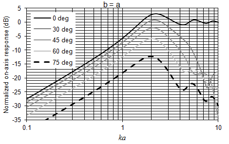
It turns out that as you make the baffle radius smaller and small these ripples start to diminish in number and intensity. When the baffle radius is less than about 1.5 to 2 times the radius of the radiating surface of the driver, they more or less disappear completely. You can verify this with models and measurements pretty easily. Or you can look at SL's own data from that same page:
Notice how the lighter curve, that is for the driver alone with no baffle, has no ripples? Any driver, used nude without a baffle as a dipole, with have the least amount of dipole ripple it possibly can. It's the case both on and off axis. That makes using it, integrating it with the other drivers, and designing the crossover much easier.
There is a series of simulation results presented on SL's web site about this subject here:
Electro-acoustic models
Scroll down (around 1/3rd of the way down the page) and look for the figures under the caption "A3-5".
Last edited:
I think the distance is still the factor, as you say, I queried Allen's sims when he posted them, I said he was "lucky" but he thinks something is going on. This should be easy enough for someone who knows what they are doing to simulate it, I don't. https://www.diyaudio.com/forums/multi-way/361169-polar-response-frame-ob-speakers-8.html#post6370538I think the question here is, does a torus mitigate the bad disc diffraction somehow? Maybe it does but there is still the cancellation null equal to the round trip radial travel front to back at half-wave.
A torus can be considered a very large radius round over edge which should eliminate diffraction.
Last edited:
Did the link I posted not take you there?
Ha! Sorry! I went directly from "Take a look..." to taking a look, and then on to your second paragraph. Totally missed the linkage in your first paragraph.
I was in two minds which forum to post in, but I'm most interested in seeing what can be got out of a full-range driver in an open baffle.Similar idea to the roll backs on large stand alone horns.
I can see an advantage for open baffle if you want to gain more acoustic output from a wider baffle...but you also increase center to center distance to the next driver. It might be interesting for a full-range driver or coaxial.
What might make for a cool system is this torus idea with a medium sized (e.g. 6") fullranger in it, and below that an upfiring closed box subwoofer with driver very close to the bottom of the torous, kind of like a slot-loaded driver, as a monopole. If a large torus can be used it could extend the useful dipole range of the fullranger down to e.g. 300Hz, with a transition to monopole below that. I think Juhazi uses a closed box sub in his system but I do not know the crossover point. The key would be making the torus large enough to support the 6" driver as a dipole low enough in frequency. And you would have to live with that look in your room! Can't be any worse that my system with lots of drivers hung by wires...
One of the main reasons SL went with open baffle was to eliminate the box and the problems it causes. Another part of the idea, and why I used that specific diagram, is to use two drivers back to back, this increases distance again which may, or may not, cause problems, but it has the advantage of identical front and rear radiation.

- Home
- Loudspeakers
- Full Range
- Did Siegfried Linkwitz miss a trick?