So what's actually happening? Earl has been explaining it to me here, https://www.diyaudio.com/forums/mul...d-diffraction-baffle-edge-10.html#post6382802 but I'm not sure I'm grasping it properly, I'm pretty sure I'm not......
I read his comment. I think I understand it. There will be diffraction from the disc edge that should appear in the polars for a real disc with thickness. When I measure my speakers I can never escape diffraction showing up in the polars. I'll generate a simple disc for comparison.
Baffle edge diffraction with dipole radiationAh, I see what you are talking about. Take a "donut" torus. Install a baffle inside of the hole in the middle, then install a driver in that. Is that correct? Like this:
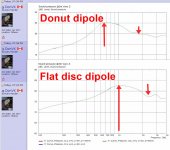
Does he mean other than the cause of the ripples that appear on axis above the dipole peak? And, why aren't they showing up with the torus, does my post(s) that follows his make any sense?")
How thick is your baffle. If its very thin you won't see the diffraction at the edge because its coincident from the front and back. It should still appear in the polars.
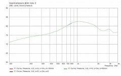
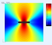
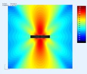
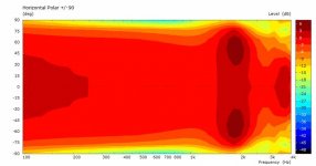
A flat disk with the inside and outside edges left sharp to promote diffraction. Same 6.5in driver as before but the disk is smaller as well.
Same 6.5in driver as before but the disk is smaller as well.Attachments
-
 ObsField-Torroid2@3K1Hz.jpg34.5 KB · Views: 251
 -
 FR-Torroid2@3m.jpg31.9 KB · Views: 247
 -
 Hpolar-Torroid2@3m.jpg22 KB · Views: 243
 -
 ObsField-Torroid2@300Hz.jpg29.4 KB · Views: 252
 -
 ObsField-Torroid2@1KHz.jpg31.1 KB · Views: 68
 -
 ObsField-Torroid2@2K7Hz.jpg37.1 KB · Views: 71
 -
 ObsField-Torroid2@3K3Hz.jpg35.1 KB · Views: 78
I still don't understand why there appears to be no on-axis interference nulls with the torus, I thought Earl was saying it was due to there being no diffraction?
He said "When a circular baffle is used in a dipole there will be on axis ripples from the edge diffraction, which will move lower as the radius of the baffle gets larger, going away for an infinite baffle. With a torus there won't be any significant diffraction (a small amount at LFs) so there won't be any axial aberrations. The directivity will change however - from an infinite baffle."
He said "When a circular baffle is used in a dipole there will be on axis ripples from the edge diffraction, which will move lower as the radius of the baffle gets larger, going away for an infinite baffle. With a torus there won't be any significant diffraction (a small amount at LFs) so there won't be any axial aberrations. The directivity will change however - from an infinite baffle."
Last edited:
Firstly, diffraction is not what gives rise to oscillations in the on or off axis response from a dipole. In a boxed loudspeaker that IS what is causing the oscillations at the top of and above the baffle step, and the more regular the distance to the edge the worse these will be. In a dipole speaker it is front-to-back pathlength differences that give rise to cancellation or addition of the front and rear waves, and these result in the oscillations. Using a toroidal baffle shape will not change that.
A torus baffle does appear to change that, which also seems to suggest that the oscillations are caused by diffraction. The question becomes, if it's not due to diffraction, how is the wave from one side of the baffle travelling around to the other side?
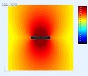
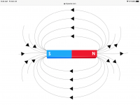
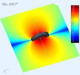
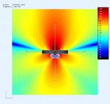
I know this is a magnetic field diagram but it represents what I think happens, the frequencies match up rolling around the torus meeting up to form the nulls? Maybe diffracting on themselves if that’s even possible?
Attachments
Last edited:
I know this is a magnetic field diagram but it represents what I think happens, the frequencies match up rolling around the torus meeting up to form the nulls? Maybe diffracting on themselves if that’s even possible?
What I found very useful was playing with the ripple tank simulation. It's fiddly, but with a little perseverance you can see what's happening.
In terms of construction, why not use papier mache on the tire inner tube to create the torus. Do two halves and join them together, with the flat baffle with the speaker on it in the centre.
Yes, I'd thought of using something like this that member TNT had used to make a spherical speaker. ModRoc Plaster of Paris Bandage Rolls - Baker Ross
Or use it on the inside of a suitable tyre, which is smooth, as a mould.
I still don't understand why there appears to be no on-axis interference nulls with the torus, I thought Earl was saying it was due to there being no diffraction?
He said "When a circular baffle is used in a dipole there will be on axis ripples from the edge diffraction, which will move lower as the radius of the baffle gets larger, going away for an infinite baffle. With a torus there won't be any significant diffraction (a small amount at LFs) so there won't be any axial aberrations. The directivity will change however - from an infinite baffle."
Its because of a simplification I did for the driver. I noticed the lateral nulls did not extend low enough and its being fixed.
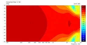
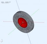
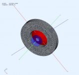
This is an update to the simple disc presented earlier. The driver membrane in the earlier model was too simplified (ie. mirrored) and did not operate properly in OB config. The lateral null now extends to lower freq. I'm usually only interested in one side of the driver
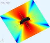
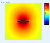
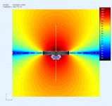
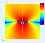
The disc ID=150mm, OD=300mm, T=40mm. There is a cone woofer model now mounted flush with the front. As the frequency increases the rear sound field will get diffracted off the magnet. There is some "whitespace" around the magnet, you can safely ignore, its just a visual artifact that did not effect the calculation.
Does this look more reasonable ?
.
Attachments
-
 DiscFrontView.jpg56.5 KB · Views: 223
 -
 DiscRearView.jpg60.1 KB · Views: 220
 -
 DiscFR@3m.jpg34.4 KB · Views: 226
 -
 DiscPolar@3m.jpg25.9 KB · Views: 224
 -
 ObsFieldFront@300Hz.jpg39.7 KB · Views: 82
 -
 ObsFieldDisc@500Khz.jpg38.9 KB · Views: 82
 -
 ObsFieldFront@1K5Hz.jpg38.7 KB · Views: 85
 -
 ObsFieldFront@2K7Hz.jpg37.8 KB · Views: 89
A torus baffle does appear to change that, which also seems to suggest that the oscillations are caused by diffraction. The question becomes, if it's not due to diffraction, how is the wave from one side of the baffle travelling around to the other side?
Let me post and answer some questions to lead you through how I think about diffraction in dipoles (and other systems too).
Q: How is the wave from one side of the baffle traveling around to the other side?
A: This depends on the ratio of the size of the radiating surface of the transducer and the size of the baffle. At low frequencies at least, the baffle is too small to change the propagation of the wave, and the source is small compared to the wavelength, so the wavefront propagates everwhere like a monopole in free space. At higher frequencies where edges can cause diffraction, the wave will still travel "around" the edge of the baffle to the other side but it no longer strictly a monopole because of the effect of the baffle and edge diffraction. At high frequencies the size of the radiating surface compared to the wavelength causes beaming and the baffle is not well illuminated, so wave propagation is no making it "around" the baffle to the other side (well not very much of it at least).
Q: What is causing the "oscillations" in the response of a dipole
A: These oscillations are caused by the interference, constructive and destructive, of the wavefronts generated from the front and back of the transducer when they meet out in the farfield. This depends on the path-lengths taken (which determines the relative phase angle when they meet). Wave that are in phase meet and add, and when out of phase cancel. If there are a variety of different pathlength taken, you have to add up all the different contributions from each. This is why the baffle shape and driver location on the baffle both influence the dipole pattern.
Q: What about diffraction in open baffle and dipole systems?
A: Without a doubt there is diffraction occurring, but that is not the primary reason behind the dipole pattern.
Background:
First, let's examine the two-monopole model of a dipole. This is simply two monopoles, one out of phase with the other and separated by a distance in open space. There aren't any surfaces to diffract the wavefronts, so no diffraction can be present. Here are the predicted responses of this model, which is described in more detail HERE:
This shows the effect of the wavefronts generated by the two sources as they interact, for several angle on and off axis. Without including diffraction, the model correctly predicts a dipole pattern (at least for low frequencies).
Moving from this model to a real system with a real driver on a finite baffle, we DO see this response shape up to a frequency which is about where the lowest "dipole peak" is found (e.g. 680Hz in the image above). This region encompasses both low and medium frequencies, the latter of which SHOULD show some diffraction even if it has only a modest effect. But real systems don't show these effects in this frequency range. It's not until at or above the dipole peak that you start to see the effects of baffle diffraction appear, and only if/when the baffle width is at least about 1.5 to 2 times the width of the radiating surface of the driver. This last point is very important, and I think it is a great teaching tool about diffraction itself. So I will delve into that now.
Here is a classic illustration of diffraction from an edge.
In the illustration, there is a wave traveling "downwards" where it encounters an edge. The wave diffracts at the edge. Behind the barrier forming the edge, you can detect/measure the wave, so it is often said that the wave "wraps around" the edge. But the illustration shows a more complete picture. What happens is that when a propagating wave encounters a change in the size of the "space" that it is traveling through, diffraction occurs. The diffraction itself generates a "new" source at the edge that radiates omnidirectionally, and the sum of this new source and the original source become the new acoustic field. Because this happens most dramatically and is localized in time and space when the edge is sharp, this is most often used as an illustration of this effect. But there is still diffraction from a slowly curving edge, too. What happens is that the curved opening of space along the edge smears out the newly created diffraction source that is localized in time and space for a sharp edge, into many different weaker sources that are now separated in both time and space along the edge as the impinging wave passes by. And these new sources continue to illuminate the "backside" of the curved edge (if there is one) and the sum of all of these sources now becomes the acoustic field.
So, diffraction is NOT removed when curved edges are used, it is only "smeared out" so that it is much more difficult to observe, sometimes to the point of "disappearing". It's like when you make a indoor nearfield measurement of a driver. The reflections from surfaces (walls, etc) are still reaching the microphone but compared to the driver's output are significantly reduced - for all practical purposes they have "disappeared". But there are definitely still there! Just too small to make any significant impact compared to the rest of the signal.
Getting back to what I said above:
When you make the baffle "small" so that it is not much larger than the driver itself, you also get a "smearing" of diffraction because the source that is illuminating the edge is no longer point-like, so it is now the sources that are distributed in space (across the entire surface of the diaphragm) and thus the time it takes them to reach the edge is also smeared out in time. This is why a nude driver (no baffle at all) has no observable diffraction signature. In fact, the larger the driver, the more this is true. The other end of the spectrum is the point source (or small source) in a relatively large baffle compared to the source size. This will have a strong diffraction occurring at the edge. This is the situation when there is a small driver (sometimes a fullranger) in a large baffle - expect diffraction problems.It's not until at or above the dipole peak that you start to see the effects of baffle diffraction appear, and only if/when the baffle width is at least about 1.5 to 2 times the width of the radiating surface of the driver.
What about the torus baffle shape?
I view the torus as an interesting combination that might actually work to reduce the amount of observed diffraction for small drivers in relatively large baffles. The curved edge of the torus will smear out the diffraction signature AND will provide a long pathlength between front and rear that can help to reduce the dipole losses.
At the same time, I do not expect the torus to do anything to the dipole pattern itself. A low frequencies the front and rear waves can still propagate everywhere and combine to forum the dipole response. At higher frequencies they waves can still "wrap" around the edges of the torus. It's only in a critical frequency band where the smearing of the wavefronts along the curved edge might lead to some interest changes. Note sure. One way to prevent front and rear wave interaction is to shape the "torus" into a horn or strong waveguide that has high directivity. At that point it will likely not strictly be a true torus and I am not sure what others have in mind for the "shape" exactly.
I do have some experimental data that suggests that MIGHT be possible. I have constructed a dipole from two 1" dome tweeters in small (circa 4") waveguides. From what I can tell, and guess, around 1kHz the separation distance just happens to be enough for constructive interference, and the SPL is raised there. If the real system followed the two-monopole model, as frequency increases there would be a series of peaks and nulls. Instead there are none at all. I believe that in this frequency region the waveguide becomes effective and the front and rear waves no longer wrap around to the opposite side. You get a very nice, near constant directivity pattern from the pair! Maybe these effects can be scaled up in size for larger drivers?
What is interesting about the two-domes back-to-back as dipole is that the measurement data do not show any appreciable diffraction effects even though the outer edge of the waveguide is just hanging out in space and separated by about 2" from the other waveguide edge. So either the waveguide is working really well, or the front and rear diffraction "cancel", or some combination of both that depends on frequency.
- Home
- Loudspeakers
- Full Range
- Did Siegfried Linkwitz miss a trick?