I followed the design by Rudolf in post #13 below to build a pair of small open baffle speakers
https://www.diyaudio.com/forums/full-range/240012-baffle-2.html
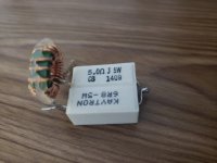
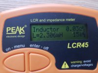
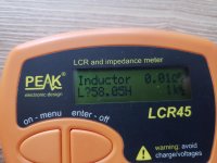
For the baffle step circuit, I could not source a 3.3mh inductor, so I used a 2.4mh instead in parallel with a 12 ohm resistor.
(photo attached)
Adding this to the fullrange driver creates a lot of distortion in the low frequencies (similar to voice coil rubbing).
I tried adding hot glue on the coil, but did not help.
Does anyone know what the issue could be?
Thanks in advance
https://www.diyaudio.com/forums/full-range/240012-baffle-2.html
For the baffle step circuit, I could not source a 3.3mh inductor, so I used a 2.4mh instead in parallel with a 12 ohm resistor.
(photo attached)
Adding this to the fullrange driver creates a lot of distortion in the low frequencies (similar to voice coil rubbing).
I tried adding hot glue on the coil, but did not help.
Does anyone know what the issue could be?
Thanks in advance
Attachments
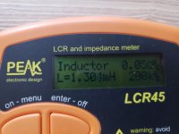
The core may be rated for 3 amps at 100 KHz but go down to 50 Hz and it could easily saturate at 20 mA. If you have a scope, signal generator, power amp and power resistor (5 ohms will work) it's easy enough to check if the core is saturating at lower frequencies. Connect the equipment in series in an appropriate manner and connect the scope probe across the resistor, when the core saturates you'll see a step in the sine wave. Use Ohm's law to solve for the current that saturation occurs at.
Coil and resistor type have nothing to do with your problem!
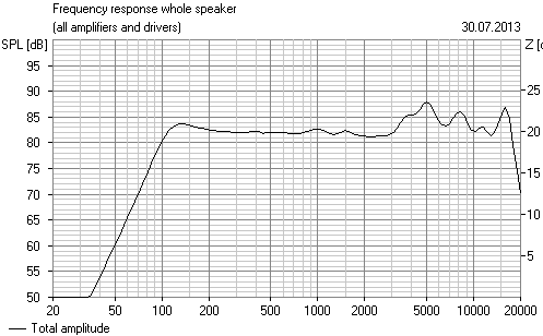
Rudolf's small baffle speakers were sitting on a desk/table which works as extra baffle, and still response below 100Hz drops like stone. The driver very easily must work too hard and it reaches mechanical excursion limit (Xmech) easily and starts clonking. Even before that there will be rubbing noise from coil/magnet gap in many cases
Guru tells more about it here Tech
Coil and resistor type have nothing to do with your problem!
Just sharing my experience on the topic... yes it does.
Using the kind of inductor posted, I get all sorts of sound artefacts while doing a sweep in REW in the lower to midrange.
If I use a real air-core inductor, the artefacts go away.
Yes that type of coil is not suitable for crossovers.
Anyway the real problem to my understanding is that a small driver is asked to produce low frequencies as dipole.
Baffle step (or actually loss) compensation with a serial coil is 1st order lowpass by nature and it will attenuate mid and high frequency (sensitivity) When the driver is asked to put out "normal" spl fullrange , it is driver to extreme excursion in bass-low mid very easily.
This is main reason why dipole speakers must be at least 2-way with large bass driver(s)
Rudolf Finke's homepage Dipolplus - Alles über offene Schallwände
Last edited:
Thanks perceval, for confirming that these inductors are in fact problematic.
And thanks Juhazi, for bringing up the issue of driver excursion.
The distortion I heard was very similar to voice coil rubbing.
I hope that this won't be the case with good inductors, especially since the drivers are 1 m away from me and I won't be listening at loud volumes.
These drivers were also used in OB using a similar crossover (10 ohm and 2mH, instead of 12 ohm and 3.3mH)
OB-5’s | Parts Express Project Gallery
For 4 ohm drivers, I found that this 1st order low pass is 193 Hz for 3.3mH inductor and 318 Hz for 2mH inductor.
Maybe the high/mid attenuation is more due to the 12 ohm resistor instead of 10 ohm, but can it make such a difference to create excursion issues?
- Status
- This old topic is closed. If you want to reopen this topic, contact a moderator using the "Report Post" button.
- Home
- Loudspeakers
- Full Range
- Open baffle step compensation on fullrange adds distortion