I've fallen into the rabbit hole of building an array of SB65WBAC25-4 drivers.
My current main speker is a 3-way and the response differs a lot when not in the sweet spot. CBTs seem to perform well here but I like dipoles hence a dipole CBT.
I've based the speaker on the following papers by Keele:
http://faculty.tru.ca/rtaylor/publications/cbt_dipole.pdf
http://faculty.tru.ca/rtaylor/publications/dipole_cbt_implementation.pdf
I want to try a CBT-shaded 70 degree circular arc dipole with 22 drivers in each speaker. My experiments so far have shown promise.
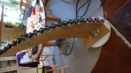
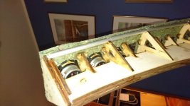
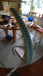
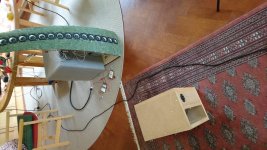
The first image is the first prototype. When taking the photo I was comparing having half drivers inverted vs all same direction. All same direction outwards measured far better. The prototype has 4 banks, which I realized with 1 resistor and 3 channels.
The next step is to build the real ersion, I just got my package of laser cut plywood =)
Along the outer spine edges I'll glue a 10mm round alu tube bent to match the speaker and then cover the whole front with a layer or more of wool felt. Should give me at least 6 dB more efficiency on the low end. (I got 10 dB with only 4 drivers). And to make it look nice I want to try and see if I can taper the baffle width. In theory it will counterract the issue that around fs the driver impedance peak will overpower the crossover. The width of the baffle around each driver is proportionally same as the attenuation: half width equals half voltage.
The final speaker / next prototype will have, well, 9 banks of attenuation. I want to keep the attenuation at high fequencies so I've planned to add inductors to the 10 ohm resistors.
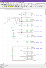
The attenuation is cosine shading like they used in implementation in the paper. I made a spreadsheet to calculate the attenuation for each driver: CBT shading - Google Sheets
Because I know nothing of CAD I wrote a python script that outputs a bitmap of all the parts, then I loaded it into Inkscape and converted it into lines. If anyone wants it I can share the code but beware, it is kinda ugly")
My current main speker is a 3-way and the response differs a lot when not in the sweet spot. CBTs seem to perform well here but I like dipoles hence a dipole CBT.
I've based the speaker on the following papers by Keele:
http://faculty.tru.ca/rtaylor/publications/cbt_dipole.pdf
http://faculty.tru.ca/rtaylor/publications/dipole_cbt_implementation.pdf
I want to try a CBT-shaded 70 degree circular arc dipole with 22 drivers in each speaker. My experiments so far have shown promise.
The first image is the first prototype. When taking the photo I was comparing having half drivers inverted vs all same direction. All same direction outwards measured far better. The prototype has 4 banks, which I realized with 1 resistor and 3 channels.
The next step is to build the real ersion, I just got my package of laser cut plywood =)
Along the outer spine edges I'll glue a 10mm round alu tube bent to match the speaker and then cover the whole front with a layer or more of wool felt. Should give me at least 6 dB more efficiency on the low end. (I got 10 dB with only 4 drivers). And to make it look nice I want to try and see if I can taper the baffle width. In theory it will counterract the issue that around fs the driver impedance peak will overpower the crossover. The width of the baffle around each driver is proportionally same as the attenuation: half width equals half voltage.
The final speaker / next prototype will have, well, 9 banks of attenuation. I want to keep the attenuation at high fequencies so I've planned to add inductors to the 10 ohm resistors.
The attenuation is cosine shading like they used in implementation in the paper. I made a spreadsheet to calculate the attenuation for each driver: CBT shading - Google Sheets
Because I know nothing of CAD I wrote a python script that outputs a bitmap of all the parts, then I loaded it into Inkscape and converted it into lines. If anyone wants it I can share the code but beware, it is kinda ugly
Attachments
Last edited:
Kudos to your efforts to construct a dipole CBT. I had a look, thanks to Don Keele, at the 2017 papers coauthored by Don and the Canadian researchers. I proceeded with my Modified CBT24 project because I wished to have a shorter path to a living room speaker versus working via the dipole route.
You likely will need both dipole subwoofers and midranges to cover the low end of the frequency band as open back SB65s will not cover much into the lower 100s Hz area. I'll be interested in your progress.
My New Line Array--It's a Modified CBT24
You likely will need both dipole subwoofers and midranges to cover the low end of the frequency band as open back SB65s will not cover much into the lower 100s Hz area. I'll be interested in your progress.
My New Line Array--It's a Modified CBT24
Ok, that's something different.
Will they be subwoofer supported?
Of course, I'm not crazy enough to run the 2.5" drivers as dipoles without some help on the bottom =)
Kudos to your efforts to construct a dipole CBT. I had a look, thanks to Don Keele, at the 2017 papers coauthored by Don and the Canadian researchers. I proceeded with my Modified CBT24 project because I wished to have a shorter path to a living room speaker versus working via the dipole route.
You likely will need both dipole subwoofers and midranges to cover the low end of the frequency band as open back SB65s will not cover much into the lower 100s Hz area. I'll be interested in your progress.
My New Line Array--It's a Modified CBT24
Yup, your thread was the main reason I tried the SB65. It really is a great driver.
I've played around with Linkwitz SPL_MAX spreadsheet and while it is not quite an apples to apples comparison I lowered to 16 drivers due to the shading and set the baffle width. In that projection I should hit xmax at around 100 dB @ 140 hz which should be plenty given a crossover somewhere in the 120 hz - 200 hz range.
The project for next weekend is to try it in practice with the wool baffle and all. I have a pair of W-frame dipole woofers and ideally I want to keep it a 2-way. The plan is to place them just behind the speaker on top of the base.
The big question is how far down they will perform well, can I push them down to 140 hz? Will the woofer integrate well at 140? My preliminary measurements have shown that I can push the woofer crossover up to 200 hz and still have a decent result but lower is probably better.
I doubt that pushing the open back SB65s into the 140 Hz region is in your future unless you aggressively equalize. Working with a sealed box SB65 in my Modified CBT24 the 3 dB down value frequency is 140 Hz. I crossed the CBT arrays to the sealed box woofers at 125 Hz with modest EQ.
I have never built a W-frame dipole woofer but I have built H-frame dipole woofers which could be used to 200 Hz. Perhaps you will have good luck with your open back SB65s but 200 Hz would be a good goal for your merge.
Good luck!
I have never built a W-frame dipole woofer but I have built H-frame dipole woofers which could be used to 200 Hz. Perhaps you will have good luck with your open back SB65s but 200 Hz would be a good goal for your merge.
Good luck!
Last edited:
I also have the SB65, and love them too.
I'd have to side with Jim here... The SB65 is not happy playing in the lower range.
Since you are shading them, some of the drivers will be pushed harder than others, and it will show in distortion measurements, and be heard as well.
I wouldn't go lower than 200Hz... myself, after having lived with the SB65 for more than a year, I'd aim even higher, like 300Hz.
I doubt that pushing the open back SB65s into the 140 Hz region is in your future unless you aggressively equalize. Working with a sealed box SB65 in my Modified CBT24 the 3 dB down value frequency is 140 Hz. I crossed the CBT arrays to the sealed box woofers at 125 Hz with modest EQ.
I have never built a W-frame dipole woofer but I have built H-frame dipole woofers which could be used to 200 Hz. Perhaps you will have good luck with your open back SB65s but 200 Hz would be a good goal for your merge.
Good luck!
I also have the SB65, and love them too.
I'd have to side with Jim here... The SB65 is not happy playing in the lower range.
Since you are shading them, some of the drivers will be pushed harder than others, and it will show in distortion measurements, and be heard as well.
I wouldn't go lower than 200Hz... myself, after having lived with the SB65 for more than a year, I'd aim even higher, like 300Hz.
Yup, I'm not yet convinced it will play nice below 200 hz. In theory the normal 6 dB rolloff / oct should become a 3 dB due to it being a shaded CBT. At least down to ~ 120 hz. And on top of that the wool baffle should increase efficiency by quite a bit. In a normal non-cbt configuration I increased the low end efficiency by 10 dB with a ~ 30 cm wide wool baffle. Reality, however, has a nice way of demolishing nice theories
I have tried to cross to one of the subs placed behind at 200 hz and while higher than ideal it does work without major issues. If that doesn't work either then I'll have to go multiway. Or probably first try to redesign the sub to work with a higher crossover.
The plan for this weekend is to build it and measure the distortion. Then we'll see how it actually performs and what it can do.
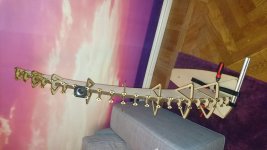
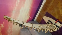
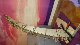
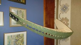
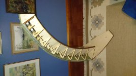
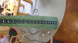
Sadly I did not get far enough to get to measure distortion. I did get some progress though and I like the look of it so far.
Next step is to mount all the drivers, connect the shading and then it is time to measure distortion =)
Next step is to mount all the drivers, connect the shading and then it is time to measure distortion =)
Attachments
Very nice project! Do not forget to also have a look at Keele's site:... I've based the speaker on the following papers by Keele:
http://faculty.tru.ca/rtaylor/publications/cbt_dipole.pdf
http://faculty.tru.ca/rtaylor/publications/dipole_cbt_implementation.pdf
...
AES Papers -- Official website of D.B.Keele
The references of AES Papers No. 29,32,33,34,38 and 43 of the years 2002 ... 2010 referring to CBT' array might be enlightening everyone diving into CBT arrays. It's really a must-read, your compulsory flashlight inside your rabbit hole. But I think you hopefully already know these papers.
Last edited:
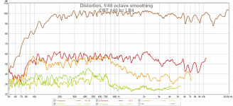
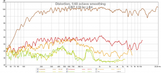
We have measurements!
This is indoors @ 100 dB @ 1m distance @ 1m height.
Apart from a DSP 18 dB highpass at 140 / 170 hz there is no EQ applied. And if it performs like this it's not like much more will be needed.
And based on the measurements crossing at either 140 or 170 hz is no problem at all. Although 170 hz is probably a little better as we cut off that slightly rising distortion as long as I can combine it with the sub without issues.
Attachments
Looking good there
Sound?
//
Nice =)
The sound is very consistent too when walking around in the room, reminds me of my Carlsson OA-5 clone. I really like that, it was one of the things i really liked with that speaker.
Wow, no dipole peak to take care off. Very nice! I hope to get good results with your felt technique on my dipole experiment.
Yup, wool takes care of the dipole peaks. At least in the current setup. If front-back dispersion is "too good" then a wider wool baffle still gets the dipole peak problem, say if you use a neo8 / neo3 then a baffle wider than a few cm more than the drivers start to hurt more than they help.
Since the speaker works great the next step is to add the subs, and they do not look nice when placed behind the speaker
In the photos I have flipped the sub because if I had it the normal orientation it was 45 cm wide and looked huuge. Not that visually appealing. Right now it is still 33 cm wide which looks a bit... ugly.
The current idea is to abandon the W-frame design and use a N-frame (like the smaller one in the image) but stack 2 on top of each other. The force cancellation won't be as good but then I can reduce the width to 22 cm. That should make it more stealthy and to make it look more nice I'll test adding curves and roundings all over so it isn't as square and sharp. Will probably fit in better with the smooth curves of the main speaker =)
Attachments
Another thing also, I measured the efficiency @ 1m from bottom @ 1m up and there it was about 86 dB @ 1W.
So the measurements in the post above was at about 20W.
The nominal impedance of the speaker is 8 ohm, it drops to a minimum of about 7 ohm @ 500 hz.
So the measurements in the post above was at about 20W.
The nominal impedance of the speaker is 8 ohm, it drops to a minimum of about 7 ohm @ 500 hz.
OllBoll, Very nice project indeed. Probably a first DIY Dipole CBT at diyaudio.
Do you think making alternate drivers sealed will improve the low end without sacrificing the CBT nature? The response would be like Nola Brio Trio or Linkwitz LXMini in a line array format.
Do you think making alternate drivers sealed will improve the low end without sacrificing the CBT nature? The response would be like Nola Brio Trio or Linkwitz LXMini in a line array format.
Last edited:
OllBoll, Very nice project indeed. Probably a first DIY Dipole CBT at diyaudio.
Do you think making alternate drivers sealed will improve the low end without sacrificing the CBT nature? The response would be like Nola Brio Trio or Linkwitz LXMini in a line array format.
So basically make a cardioid CBT? Should work, the low frequency output should be about equal as the limiting factor will be the output of the dipole drivers.
The more I think about it the more I think that if you want cardioid CBT I think every second driver as sealed is a really nifty way to do it.
Another option would be to run all the drivers sealed but for every 2 drivers facing forwards you add another driver facing backwards wired out of phase of the other two. In this case the crossover would be more simple as you can run the same shading to all 3 drivers. A lot easier to build the enclosure too. Would require 50% more drivers though and it is possible the added distance to the drivers would create dipole peak problems. Or it might not and just work better, only way to find out is to try it and measure
Last edited:
I have been busy experimenting with amplifiers for the last weekends but I think it is time to do some more experiments this weekend.
While it looks cool I'm not 100% sold on a ground plane version and so I want to try a 35 degree non-ground plane one. Would be nice to have maximum efficiency at listening level too and not at floor level. The current idea is to experimentally just rotate the the current array 35 degrees and baste some more wool to make the baffle distances the same along the whole array. Should be good enough for testing.
I also believe I have calculated the shading network incorrectly, I believe I've attenuated way too much. In the current setup I have shaded the voltage and not the power... After taking the square root of all the shadings a lot more power goes to the shaded drivers =)
- Home
- Loudspeakers
- Full Range
- CBT Dipole with SB65WBAC25-4