Hi all! Thanks so much for such kind words, as always. I'm sorry it's been so long since the last post - quite a bit has happened lately. Hey djn, nothing special for the power supply, they deserve much better:
SGC 7v Linear Power Supply 15W (ultraRendu, microRendu, ultraDigital) – Small Green Computer
I began my effort with the magnetic circuit years ago by deciding on a power requirement. While lowering the motor power will raise the Qts, I've tried to put that out of mind. The speaker sounds great with 12VDC to the motor, but varying the power to alter the performance is definitely a viable option.")
A few weeks ago a great guy here linked me to a DIY audio facebook group. I made a first post to his group - it was popular and shared around quite a bit to others, and that's generated a lot of interest. That's why I've been busy the past few weeks. From the reactions I've read, people generally enjoy the loudspeaker, but it's the driver I'm getting pricing inquiries about.
So far, I've leaned toward not selling the raw drivers. It invites a measure of risk, particularly for an unusual driver like this one. Common drivers do not have a 33-pound electromagnet married to a slender frame, nor do most have the atypical T/S params this one does. The Qts is very low, the Fs is very low, the Vas is very high... It's hard not to worry that a few people will make improper use of the mounting point to support the electromagnet, or will design a speaker ill-suited to the driver's strengths - and in either case, may come away disappointed. When I control the design and build, I enjoy full confidence in the result. If I'm going to sell raw drivers, well... I'll have to give much of that control up.
Rather than turn away interest in the driver however, I've decided to price and sell 2-3 initial pairs to begin with, and I'll continue selling them if it goes well. To set myself up for success and put something of highest quality into these first buyer's hands, I'll need/want to do a few things:
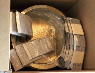
After spending a few days in Fusion 360 doing the design work, I put in an order for new brass and aluminum frame parts - enough to produce eight sets of drivers. After a day tapping and threading arms, the box of material looks something like this:
http://kensonger.com/field_coil/diyaudio/new_frame_parts.jpg
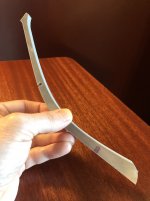
The aluminum arms are 20% thicker, and the footing that attaches to the rim has a 300% larger surface area and can accept a longer M4 bolt. The rims are 30% thicker as well. Right off the water-jet the arms look like this:
http://kensonger.com/field_coil/diyaudio/new_arm.jpg
While it retains it's looks, this new frame is also very strong. I don't recommend letting it solely bear the weight of the motor, but you know... it may be able to. It'll be stress-tested for reasonable limits in the next couple of weeks.
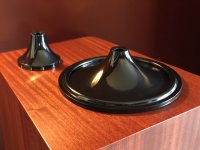
Lengthening the throat of the cones meant printing, sanding and sealing new pairs of molds.
http://kensonger.com/field_coil/diyaudio/new_molds.jpg
Extending the curvature of the cone to gradually terminate vertically with the former may likely have a positive effect on the sound of the driver. It makes sense to me that a seamless transition from former to cone should transfer voice coil energy more efficiently, and the cone geometry should be a little more rigid. The motion of the moving assembly may also be more linear, with the cone extending right down to the plane of the spider suspension.
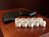
Re-coning a few driver pairs means creating a new batch of voice coils as well, and cutting new lambskin surrounds.
http://kensonger.com/field_coil/diyaudio/surrounds_and_voice_coils.jpg
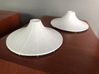
The first cones were laid onto the new molds today - it was a mild afternoon in Portland, so I left the wet cones on top of a pair of prototype cabinets in front of the open balcony door to cure.
http://kensonger.com/field_coil/diyaudio/new_cones_drying.jpg
In the morning they will be bone dry, the seams will be much less pronounced, and they will be ready to be trimmed, lightly sanded to a 6 gram weight, and then sealed. About 75% of these cones turn out to be good enough for my personal taste. I'll post a pic of these and the whizzers in the next couple of days.
After laying up a next set of cones and whizzers to dry tomorrow morning, I'll be spending the rest of the day with the metal work - sanding the parts on a belt sander up to 1000 grit. A local anodizing business offers a service called 'bright dipping' for aluminum, and depending on the cost I may try it out after the final sanding. It chemically polishes aluminum to a mirror finish by fusing the topmost molecular surface of the metal - and if it works well, it will save me quite a bit of time and effort over polishing by hand.
It's an exciting time, and I am deeply grateful to have made something so many people seem to enjoy. But it's also a nervous time... these objects deliver remarkable sound because the materials are costly, the execution is uncompromising, and the design and craftsmanship are the result of thousands of hours of effort over years. Because of that, well... the driver can't be inexpensive. The accounting spreadsheet certainly proves that. And, no matter how favorably it compares with the other field coil and full-range drivers I've heard, I don't have a name. I don't have a factory floor to produce them. I'm not well-connected, and I don't have any reputation to precede me.
Lastly, I know all too well from my time with start-up companies that making something, no matter how extraordinary, doesn't at all assure that you'll succeed. I may or may not earn success, but the driver has taken on something of a life of it's own... and, it really deserves to be heard.
Let's hope I can give it that chance.
Cheers all, more soon...
SGC 7v Linear Power Supply 15W (ultraRendu, microRendu, ultraDigital) – Small Green Computer
I began my effort with the magnetic circuit years ago by deciding on a power requirement. While lowering the motor power will raise the Qts, I've tried to put that out of mind. The speaker sounds great with 12VDC to the motor, but varying the power to alter the performance is definitely a viable option.
A few weeks ago a great guy here linked me to a DIY audio facebook group. I made a first post to his group - it was popular and shared around quite a bit to others, and that's generated a lot of interest. That's why I've been busy the past few weeks. From the reactions I've read, people generally enjoy the loudspeaker, but it's the driver I'm getting pricing inquiries about.
So far, I've leaned toward not selling the raw drivers. It invites a measure of risk, particularly for an unusual driver like this one. Common drivers do not have a 33-pound electromagnet married to a slender frame, nor do most have the atypical T/S params this one does. The Qts is very low, the Fs is very low, the Vas is very high... It's hard not to worry that a few people will make improper use of the mounting point to support the electromagnet, or will design a speaker ill-suited to the driver's strengths - and in either case, may come away disappointed. When I control the design and build, I enjoy full confidence in the result. If I'm going to sell raw drivers, well... I'll have to give much of that control up.
Rather than turn away interest in the driver however, I've decided to price and sell 2-3 initial pairs to begin with, and I'll continue selling them if it goes well. To set myself up for success and put something of highest quality into these first buyer's hands, I'll need/want to do a few things:
- Meticulously spreadsheet an account of material, labor, shipping and all ancillary costs to produce one pair of drivers.
- Preserve the look of the driver, however redesign the frame for significantly increased strength and support tolerance.
- Circle back to something I've meant to do for awhile - extend the throat of the main and whizzer cones, such that the former meets the cone at the attachment of the spider instead of above it.
After spending a few days in Fusion 360 doing the design work, I put in an order for new brass and aluminum frame parts - enough to produce eight sets of drivers. After a day tapping and threading arms, the box of material looks something like this:
http://kensonger.com/field_coil/diyaudio/new_frame_parts.jpg
The aluminum arms are 20% thicker, and the footing that attaches to the rim has a 300% larger surface area and can accept a longer M4 bolt. The rims are 30% thicker as well. Right off the water-jet the arms look like this:
http://kensonger.com/field_coil/diyaudio/new_arm.jpg
While it retains it's looks, this new frame is also very strong. I don't recommend letting it solely bear the weight of the motor, but you know... it may be able to. It'll be stress-tested for reasonable limits in the next couple of weeks.
Lengthening the throat of the cones meant printing, sanding and sealing new pairs of molds.
http://kensonger.com/field_coil/diyaudio/new_molds.jpg
Extending the curvature of the cone to gradually terminate vertically with the former may likely have a positive effect on the sound of the driver. It makes sense to me that a seamless transition from former to cone should transfer voice coil energy more efficiently, and the cone geometry should be a little more rigid. The motion of the moving assembly may also be more linear, with the cone extending right down to the plane of the spider suspension.
Re-coning a few driver pairs means creating a new batch of voice coils as well, and cutting new lambskin surrounds.
http://kensonger.com/field_coil/diyaudio/surrounds_and_voice_coils.jpg
The first cones were laid onto the new molds today - it was a mild afternoon in Portland, so I left the wet cones on top of a pair of prototype cabinets in front of the open balcony door to cure.
http://kensonger.com/field_coil/diyaudio/new_cones_drying.jpg
In the morning they will be bone dry, the seams will be much less pronounced, and they will be ready to be trimmed, lightly sanded to a 6 gram weight, and then sealed. About 75% of these cones turn out to be good enough for my personal taste. I'll post a pic of these and the whizzers in the next couple of days.
After laying up a next set of cones and whizzers to dry tomorrow morning, I'll be spending the rest of the day with the metal work - sanding the parts on a belt sander up to 1000 grit. A local anodizing business offers a service called 'bright dipping' for aluminum, and depending on the cost I may try it out after the final sanding. It chemically polishes aluminum to a mirror finish by fusing the topmost molecular surface of the metal - and if it works well, it will save me quite a bit of time and effort over polishing by hand.
It's an exciting time, and I am deeply grateful to have made something so many people seem to enjoy. But it's also a nervous time... these objects deliver remarkable sound because the materials are costly, the execution is uncompromising, and the design and craftsmanship are the result of thousands of hours of effort over years. Because of that, well... the driver can't be inexpensive. The accounting spreadsheet certainly proves that. And, no matter how favorably it compares with the other field coil and full-range drivers I've heard, I don't have a name. I don't have a factory floor to produce them. I'm not well-connected, and I don't have any reputation to precede me.
Lastly, I know all too well from my time with start-up companies that making something, no matter how extraordinary, doesn't at all assure that you'll succeed. I may or may not earn success, but the driver has taken on something of a life of it's own... and, it really deserves to be heard.
Let's hope I can give it that chance.
Cheers all, more soon...
Attachments
Last edited:
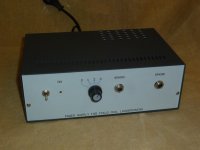
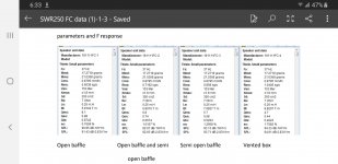
Here is the power supply I use. It has 4 settings and you can see the difference it makes in the T/S parameters. Mine is set at 4 fixed voltages but another FC drivers used variable power supplies.
What is the FB page?
What is the FB page?
Attachments
Last edited:
That's really great info djn, thanks for sharing it. During my first few years of development I used a couple of bench power supplies with variable voltage/current. I'd like to in the coming year do a two-way open baffle design that showcases the look of the driver - revisiting the target power requirement will definitely be a part of that exercise. May I ask where your power supply came from? I've been looking for a replacement for the supplies I have, and would definitely consider buying a couple of those for myself...
There are two FB groups I've joined - the original post was made in the first group below, and later shared by the admin to the second group. Both offered a ton of positive comments and interest:
Lowther Modification Support Group
Lowther Modification Support Group Public Group | Facebook
Extreme DIY Loudspeaker Building
Extreme DIY loudspeaker building. Public Group | Facebook
Hi all! Thanks so much for such kind words, as always. I'm sorry it's been so long since the last post - quite a bit has happened lately. Hey djn, nothing special for the power supply, they deserve much better:
SGC 7v Linear Power Supply 15W (ultraRendu, microRendu, ultraDigital) – Small Green Computer
I began my effort with the magnetic circuit years ago by deciding on a power requirement. While lowering the motor power will raise the Qts, I've tried to put that out of mind. The speaker sounds great with 12VDC to the motor, but varying the power to alter the performance is definitely a viable option.
A few weeks ago a great guy here linked me to a DIY audio facebook group. I made a first post to his group - it was popular and shared around quite a bit to others, and that's generated a lot of interest. That's why I've been busy the past few weeks. From the reactions I've read, people generally enjoy the loudspeaker, but it's the driver I'm getting pricing inquiries about.
So far, I've leaned toward not selling the raw drivers. It invites a measure of risk, particularly for an unusual driver like this one. Common drivers do not have a 33-pound electromagnet married to a slender frame, nor do most have the atypical T/S params this one does. The Qts is very low, the Fs is very low, the Vas is very high... It's hard not to worry that a few people will make improper use of the mounting point to support the electromagnet, or will design a speaker ill-suited to the driver's strengths - and in either case, may come away disappointed. When I control the design and build, I enjoy full confidence in the result. If I'm going to sell raw drivers, well... I'll have to give much of that control up.
Rather than turn away interest in the driver however, I've decided to price and sell 2-3 initial pairs to begin with, and I'll continue selling them if it goes well. To set myself up for success and put something of highest quality into these first buyer's hands, I'll need/want to do a few things:
- Meticulously spreadsheet an account of material, labor, shipping and all ancillary costs to produce one pair of drivers.
- Preserve the look of the driver, however redesign the frame for significantly increased strength and support tolerance.
- Circle back to something I've meant to do for awhile - extend the throat of the main and whizzer cones, such that the former meets the cone at the attachment of the spider instead of above it.
After spending a few days in Fusion 360 doing the design work, I put in an order for new brass and aluminum frame parts - enough to produce eight sets of drivers. After a day tapping and threading arms, the box of material looks something like this:
http://kensonger.com/field_coil/diyaudio/new_frame_parts.jpg
The aluminum arms are 20% thicker, and the footing that attaches to the rim has a 300% larger surface area and can accept a longer M4 bolt. The rims are 30% thicker as well. Right off the water-jet the arms look like this:
http://kensonger.com/field_coil/diyaudio/new_arm.jpg
While it retains it's looks, this new frame is also very strong. I don't recommend letting it solely bear the weight of the motor, but you know... it may be able to. It'll be stress-tested for reasonable limits in the next couple of weeks.
Lengthening the throat of the cones meant printing, sanding and sealing new pairs of molds.
http://kensonger.com/field_coil/diyaudio/new_molds.jpg
Extending the curvature of the cone to gradually terminate vertically with the former may likely have a positive effect on the sound of the driver. It makes sense to me that a seamless transition from former to cone should transfer voice coil energy more efficiently, and the cone geometry should be a little more rigid. The motion of the moving assembly may also be more linear, with the cone extending right down to the plane of the spider suspension.
Re-coning a few driver pairs means creating a new batch of voice coils as well, and cutting new lambskin surrounds.
http://kensonger.com/field_coil/diyaudio/surrounds_and_voice_coils.jpg
The first cones were laid onto the new molds today - it was a mild afternoon in Portland, so I left the wet cones on top of a pair of prototype cabinets in front of the open balcony door to cure.
http://kensonger.com/field_coil/diyaudio/new_cones_drying.jpg
In the morning they will be bone dry, the seams will be much less pronounced, and they will be ready to be trimmed, lightly sanded to a 6 gram weight, and then sealed. About 75% of these cones turn out to be good enough for my personal taste. I'll post a pic of these and the whizzers in the next couple of days.
After laying up a next set of cones and whizzers to dry tomorrow morning, I'll be spending the rest of the day with the metal work - sanding the parts on a belt sander up to 1000 grit. A local anodizing business offers a service called 'bright dipping' for aluminum, and depending on the cost I may try it out after the final sanding. It chemically polishes aluminum to a mirror finish by fusing the topmost molecular surface of the metal - and if it works well, it will save me quite a bit of time and effort over polishing by hand.
It's an exciting time, and I am deeply grateful to have made something so many people seem to enjoy. But it's also a nervous time... these objects deliver remarkable sound because the materials are costly, the execution is uncompromising, and the design and craftsmanship are the result of thousands of hours of effort over years. Because of that, well... the driver can't be inexpensive. The accounting spreadsheet certainly proves that. And, no matter how favorably it compares with the other field coil and full-range drivers I've heard, I don't have a name. I don't have a factory floor to produce them. I'm not well-connected, and I don't have any reputation to precede me.
Lastly, I know all too well from my time with start-up companies that making something, no matter how extraordinary, doesn't at all assure that you'll succeed. I may or may not earn success, but the driver has taken on something of a life of it's own... and, it really deserves to be heard.
Let's hope I can give it that chance.
Cheers all, more soon...
Hi man what is the wire diameter you have used and how many turns and how much the coil weighs. Im trying to understand how much power its dissipating in total. As you have mentioned you are using 15W supply.
Thanks so much for the wonderful compliments, all! Vitorio, I love Spain - my wife and I hope to move there some day. Have you heard Alsyvox? Such wonderful loudspeakers... Sorry for the short little installment here, but I ran out of time today and wanted to to post something nonetheless. Tomorrow, I'll have something more detailed and informative, particularly around testing methods and results, and the cabinets. Hope everyone enjoys the pics.
I thought people may want to see some images of the individual elements of the driver and the making of them in progress.
A cone mold after being printed, about an 8 hour job:
http://kensonger.com/field_coil/diyaudio/cone_mold_printed.jpeg
The printed molds are primed and sanded a few times, and then finally sealed with an acrylic cold glaze. A full set of cones drying, with a voice coil sitting on top of one of them:
http://kensonger.com/field_coil/diyaudio/cones_drying.jpeg
A trimmed voice coil, fresh off the winding assembly:
http://kensonger.com/field_coil/diyaudio/voice_coil.jpeg
A cone and voice coil assembled and ready to be centered and attached to the spider assembly:
http://kensonger.com/field_coil/diyaudio/cone_and_coil.jpeg
Water saturated leather surrounds, ready to sit in front of the fireplace and dry out. The outer excess isn't trimmed away until it's been attached to the finished cone and glued down to the basket rim:
http://kensonger.com/field_coil/diyaudio/wet_surrounds.jpeg
A solenoid right after coming off the bobbin. Next, extra epoxy is trimmed away and the coil is wrapped with a durable gaffers tape:
http://kensonger.com/field_coil/diyaudio/solenoid.jpeg
Cheers,
Ken
Doesn`t water damage the natural properties of leather softness?
Duelund already did the spider with threads so what is unique about in your approach?
Hi,
Yes, Steen has done that and others as well, but I´ m not aware of any commercial implementation. Durability and consistency of the thread used might play a role...
Ken, by the way, doesn´t use threads anymore.
Generally, the thread approach has advantages:
- very low mass
- very low emissive area
- easy to center
and disadvantages:
- no linear behaviour, or only at very small cone movements
- depending on material, questionable reliability
- risk of TSP drift with time
- depending upon production process, repeatability of driver behaviour in series production might be difficult to achieve
Personally, I see more potential in Be Yamamuras carbon spider approach, but sadly there´s not much info to find.
All the best
Mattes
If I may begin by stating the obvious, it's been a very long time. Continuing in that vein, a awful lot has happened as well, since my last post here. I'm just dipping my toes into a 4th generation of the field coil driver. It branched out in that time also, into two similar drivers for use in ported enclosure and for a new open baffle design that was completed just a couple of months ago.
I have graduated from squatting in a friend's garage to a legitimate shop space. Thanks to a seven month software gig, I've been able to outfit it with a serious CNC router, a large format 3D resin printer, a design station for CAD/CAM and testing and measurements, a Cameo 4 cutting machine, industrial buffing equipment, ample storage, and a small army of bench power tools. All of that in combination with a large, shared woodshop, and well... there isn't much I can't take on now.


The driver has evolved considerably.
The voice coil is wound with copper clad aluminum wire these days. CCA wire is less conductive and more resistive than pure copper wire, however it is much, much lighter than its copper equivalent. My voice coils at the time of my last post were about 2 grams. However, the CCA voice coils in my current work are just 0.6 grams. Feather light. The other nice thing about CCA wire is that fewer windings are necessary to reach a target resistance. Because fewer windings are needed, the Qes (and therefore, Qts) of the driver goes up. At the time of my last post, the field coil had a Qts of about .18, very low. As a result, the ported enclosure alone couldn't produce authoritative sub-bass response. To solve that problem, I was (sadly, in retrospect) using a series resistor to artificially raise system Qts. In fairness, I was getting reasonably good results. However, that big series resistor was also sucking some of the life out of the listening experience everywhere else. It was a workaround, not a real solution.
As I have mentioned in prior posts, there is no such thing as a free lunch. Because I am using fewer windings, the sensitivity of the driver has gone down. At its peak in that respect, the driver produced SPL worthy of flea-watt amplification, 96.5dB. Several iterations and two years later, that figure is down to 92.6dB, as measured in drivers completed just last month.
But, I'm definitely okay with that. The sensitivity is still quite high. The intricate resolving power of the light moving mass contributes so much to the listening experience - it's so fast. The freedom to eliminate a big resistor from the path has infused more life back into the midrange and treble. The new Qts of .44 delivers gorgeous bass response in the ported enclosure. For me... it's all nothing but a win.
It then seemed appropriate to revisit the motor steel, and come up with a new design. With fewer windings, I didn't need as deep a gap in the motor geometry to achieve the same Xmax. What's more, my nightmares have long been haunted by the notion that a voice coil may eventually experience rubbing in a customer's home. The old voice coil winding was a little shy of 5mm in height, operating in an 11mm high, 1mm wide gap. The new winding is just 3mm, and operates in a 9mm high gap. While 2mm doesn't seem like a lot, it actually increases the magnetic strength in that gap, concentrating it into a smaller area. That's allowed me to increase the gap strength to 1.7 tesla while at the same time widening the gap from 1mm to 1.2mm. That too may not seem like a big deal, but when the gap tolerance of the driver is the thickness of a dollar bill on either side of the voice coil winding... 0.2mm is a luxurious parcel of new real estate. I have better magnetic strength, higher self-damping and lower distortion... and I don't lose sleep about the voice coil rubbing any more.
Alright dear reader, I should probably stop there, just for now. So much more to come.
Hey rhythmsandy, here are a few very belated replies to your questions. Voice coil is 45 windings of .125mm CCA in two layers. I'm currently using a wonderful power supply designed for me by Whammerdyne, that is variable between 9-12.5 VDC - you can read more about it on the website if you like:
https://songeraudio.com/products#a_ps1
I like to run the ported enclosure at 11VDC, and the open baffles at 12.5VDC. While the driver can be bottomed out, you've really got to be working at it with this latest motor steel. There are several millimeters of room below the gap, and with that travel I've witnessed the drivers producing 20 cycles full of transients at a level of 95-100dB in what was a typical listening space. Physically painful volume levels. Again, it can be done... in a very large listening space, it can for sure. I've seen that happen, too.
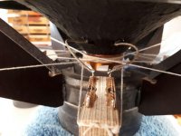
The spider isn't wholly unique. There are a few key differences, but the most salient advantage over Frederik's string spider is durability. My first spiders were string as well, long before I had become aware of the Duelund design... but I quickly pivoted away from string because it just doesn't hold up well. Frederik sets the expectation with his customers that the drivers need occasional maintenance. I can attest that without that maintenance, the voice coil loses centering in the gap, and the driver characteristics long before that unhappy day do not remain consistent over time.
I have graduated from squatting in a friend's garage to a legitimate shop space. Thanks to a seven month software gig, I've been able to outfit it with a serious CNC router, a large format 3D resin printer, a design station for CAD/CAM and testing and measurements, a Cameo 4 cutting machine, industrial buffing equipment, ample storage, and a small army of bench power tools. All of that in combination with a large, shared woodshop, and well... there isn't much I can't take on now.
The driver has evolved considerably.
The voice coil is wound with copper clad aluminum wire these days. CCA wire is less conductive and more resistive than pure copper wire, however it is much, much lighter than its copper equivalent. My voice coils at the time of my last post were about 2 grams. However, the CCA voice coils in my current work are just 0.6 grams. Feather light. The other nice thing about CCA wire is that fewer windings are necessary to reach a target resistance. Because fewer windings are needed, the Qes (and therefore, Qts) of the driver goes up. At the time of my last post, the field coil had a Qts of about .18, very low. As a result, the ported enclosure alone couldn't produce authoritative sub-bass response. To solve that problem, I was (sadly, in retrospect) using a series resistor to artificially raise system Qts. In fairness, I was getting reasonably good results. However, that big series resistor was also sucking some of the life out of the listening experience everywhere else. It was a workaround, not a real solution.
As I have mentioned in prior posts, there is no such thing as a free lunch. Because I am using fewer windings, the sensitivity of the driver has gone down. At its peak in that respect, the driver produced SPL worthy of flea-watt amplification, 96.5dB. Several iterations and two years later, that figure is down to 92.6dB, as measured in drivers completed just last month.
But, I'm definitely okay with that. The sensitivity is still quite high. The intricate resolving power of the light moving mass contributes so much to the listening experience - it's so fast. The freedom to eliminate a big resistor from the path has infused more life back into the midrange and treble. The new Qts of .44 delivers gorgeous bass response in the ported enclosure. For me... it's all nothing but a win.
It then seemed appropriate to revisit the motor steel, and come up with a new design. With fewer windings, I didn't need as deep a gap in the motor geometry to achieve the same Xmax. What's more, my nightmares have long been haunted by the notion that a voice coil may eventually experience rubbing in a customer's home. The old voice coil winding was a little shy of 5mm in height, operating in an 11mm high, 1mm wide gap. The new winding is just 3mm, and operates in a 9mm high gap. While 2mm doesn't seem like a lot, it actually increases the magnetic strength in that gap, concentrating it into a smaller area. That's allowed me to increase the gap strength to 1.7 tesla while at the same time widening the gap from 1mm to 1.2mm. That too may not seem like a big deal, but when the gap tolerance of the driver is the thickness of a dollar bill on either side of the voice coil winding... 0.2mm is a luxurious parcel of new real estate. I have better magnetic strength, higher self-damping and lower distortion... and I don't lose sleep about the voice coil rubbing any more.
Alright dear reader, I should probably stop there, just for now. So much more to come.
Hey rhythmsandy, here are a few very belated replies to your questions. Voice coil is 45 windings of .125mm CCA in two layers. I'm currently using a wonderful power supply designed for me by Whammerdyne, that is variable between 9-12.5 VDC - you can read more about it on the website if you like:
https://songeraudio.com/products#a_ps1
I like to run the ported enclosure at 11VDC, and the open baffles at 12.5VDC. While the driver can be bottomed out, you've really got to be working at it with this latest motor steel. There are several millimeters of room below the gap, and with that travel I've witnessed the drivers producing 20 cycles full of transients at a level of 95-100dB in what was a typical listening space. Physically painful volume levels. Again, it can be done... in a very large listening space, it can for sure. I've seen that happen, too.
The spider isn't wholly unique. There are a few key differences, but the most salient advantage over Frederik's string spider is durability. My first spiders were string as well, long before I had become aware of the Duelund design... but I quickly pivoted away from string because it just doesn't hold up well. Frederik sets the expectation with his customers that the drivers need occasional maintenance. I can attest that without that maintenance, the voice coil loses centering in the gap, and the driver characteristics long before that unhappy day do not remain consistent over time.
Feather light. T
hmm let me see few things in here. First of all using a CCAW wire is ofcourse is lighter but are you able to identify the difference? Since the field coil motors are extremely strong in the field so mass really doesn`t matter but are you able to hear the difference in improved resolution with CCAW wire? Can you pls elaborate with an example.If I may begin by stating the obvious, it's been a very long time. Continuing in that vein, a awful lot has happened as well, since my last post here. I'm just dipping my toes into a 4th generation of the field coil driver. It branched out in that time also, into two similar drivers for use in ported enclosure and for a new open baffle design that was completed just a couple of months ago.
I have graduated from squatting in a friend's garage to a legitimate shop space. Thanks to a seven month software gig, I've been able to outfit it with a serious CNC router, a large format 3D resin printer, a design station for CAD/CAM and testing and measurements, a Cameo 4 cutting machine, industrial buffing equipment, ample storage, and a small army of bench power tools. All of that in combination with a large, shared woodshop, and well... there isn't much I can't take on now.
View attachment 1082151
View attachment 1082153
The driver has evolved considerably.
The voice coil is wound with copper clad aluminum wire these days. CCA wire is less conductive and more resistive than pure copper wire, however it is much, much lighter than its copper equivalent. My voice coils at the time of my last post were about 2 grams. However, the CCA voice coils in my current work are just 0.6 grams. Feather light. The other nice thing about CCA wire is that fewer windings are necessary to reach a target resistance. Because fewer windings are needed, the Qes (and therefore, Qts) of the driver goes up. At the time of my last post, the field coil had a Qts of about .18, very low. As a result, the ported enclosure alone couldn't produce authoritative sub-bass response. To solve that problem, I was (sadly, in retrospect) using a series resistor to artificially raise system Qts. In fairness, I was getting reasonably good results. However, that big series resistor was also sucking some of the life out of the listening experience everywhere else. It was a workaround, not a real solution.
As I have mentioned in prior posts, there is no such thing as a free lunch. Because I am using fewer windings, the sensitivity of the driver has gone down. At its peak in that respect, the driver produced SPL worthy of flea-watt amplification, 96.5dB. Several iterations and two years later, that figure is down to 92.6dB, as measured in drivers completed just last month.
But, I'm definitely okay with that. The sensitivity is still quite high. The intricate resolving power of the light moving mass contributes so much to the listening experience - it's so fast. The freedom to eliminate a big resistor from the path has infused more life back into the midrange and treble. The new Qts of .44 delivers gorgeous bass response in the ported enclosure. For me... it's all nothing but a win.
It then seemed appropriate to revisit the motor steel, and come up with a new design. With fewer windings, I didn't need as deep a gap in the motor geometry to achieve the same Xmax. What's more, my nightmares have long been haunted by the notion that a voice coil may eventually experience rubbing in a customer's home. The old voice coil winding was a little shy of 5mm in height, operating in an 11mm high, 1mm wide gap. The new winding is just 3mm, and operates in a 9mm high gap. While 2mm doesn't seem like a lot, it actually increases the magnetic strength in that gap, concentrating it into a smaller area. That's allowed me to increase the gap strength to 1.7 tesla while at the same time widening the gap from 1mm to 1.2mm. That too may not seem like a big deal, but when the gap tolerance of the driver is the thickness of a dollar bill on either side of the voice coil winding... 0.2mm is a luxurious parcel of new real estate. I have better magnetic strength, higher self-damping and lower distortion... and I don't lose sleep about the voice coil rubbing any more.
Alright dear reader, I should probably stop there, just for now. So much more to come.
Hey rhythmsandy, here are a few very belated replies to your questions. Voice coil is 45 windings of .125mm CCA in two layers. I'm currently using a wonderful power supply designed for me by Whammerdyne, that is variable between 9-12.5 VDC - you can read more about it on the website if you like:
https://songeraudio.com/products#a_ps1
I like to run the ported enclosure at 11VDC, and the open baffles at 12.5VDC. While the driver can be bottomed out, you've really got to be working at it with this latest motor steel. There are several millimeters of room below the gap, and with that travel I've witnessed the drivers producing 20 cycles full of transients at a level of 95-100dB in what was a typical listening space. Physically painful volume levels. Again, it can be done... in a very large listening space, it can for sure. I've seen that happen, too.
The spider isn't wholly unique. There are a few key differences, but the most salient advantage over Frederik's string spider is durability. My first spiders were string as well, long before I had become aware of the Duelund design... but I quickly pivoted away from string because it just doesn't hold up well. Frederik sets the expectation with his customers that the drivers need occasional maintenance. I can attest that without that maintenance, the voice coil loses centering in the gap, and the driver characteristics long before that unhappy day do not remain consistent over time.
I'd love to do that, thanks for the offer @AllenB ! The old website that once hosted them has been retired since I started the thread.Some of the images in this thread have disappeared as the links have dropped out. If OP would like to restore these into the posts as attachments, the offer is here.
Hey @rhythmsandy -hmm let me see few things in here. First of all using a CCAW wire is ofcourse is lighter but are you able to identify the difference? Since the field coil motors are extremely strong in the field so mass really doesn`t matter but are you able to hear the difference in improved resolution with CCAW wire? Can you pls elaborate with an example.
While the field coil motor is very strong, mass still matters a great deal for a full range driver like this one. As an illustration, the 1.4 gram difference between the CCA voice coils and the older copper versions is more than 10% of the total moving mass. That weight savings has been instrumental in getting good frequency response in the last octave, along with a faraday ring integrated into the base of the aluminum phase plug. In my experience, transducer weight is the most important factor above 10kHz.
The change in Qts is very important as well. If you have a box modeling software to experiment with, try changing the Qts of the driver in one of your single driver designs from .18 to .43. You'll see that it makes an enormous difference with respect to bass response.
- Home
- Loudspeakers
- Full Range
- Creating a Field Coil Driver & Loudspeaker