As I still need to have the speakers close to the corners
What you thought and wrote don't match to me which is why I was trying to point out that the pattern would be affected by the absorber and position.I wasn't thinking THAT short distance.
Can you model dipoles in Vituixcad? It would sure be interesting to have a look into it.
Here "they" are going bananas... post #6085
The making of: The Two Towers (a 25 driver Full Range line array)
//
I guess the "they" are aimed at nc535 and me? 
I did not test dipoles, as I want to keep bottom end efficiency as is and in fact, if I succeed, I want to stick to the full range topology,
meaning if I can, I won't be using tweeters. And I do believe I can, as I've been quite happy with the results I got prior to any shading.
I'm hoping to test the shading and learn if that modification results in an improvement over unshaded (straight) arrays, time will tell.
Last edited:
I prefer the tight in the absorbent corner approach provided you can get tight enough looking at reflection null distance vs absorbency at that frequency if filled with absorber. The dipole thing was for when "loose" in corner - toed in near corner - where the null the dipole throws out to the side looks like the only thing that would help and of course that isn't the only thing you need to be concerned about...
Another take on this, trying to share the load better between the drivers in the low end:
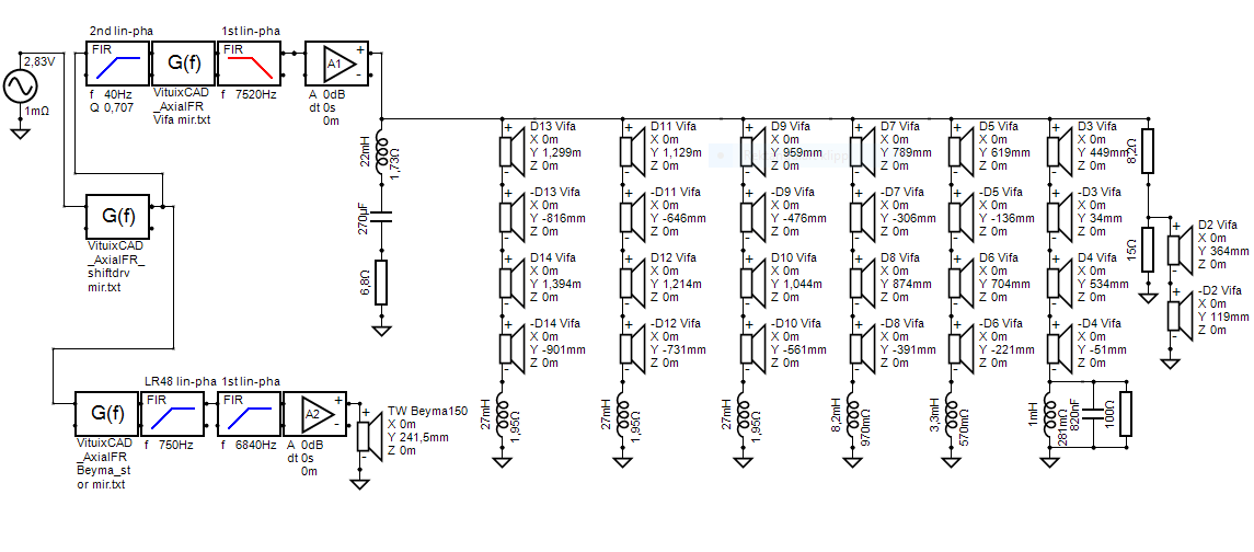
Now groups of 4 driver with only 2 in the centre group (attenuated with resistors to match the response with the other groups).
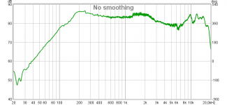
Response like this:
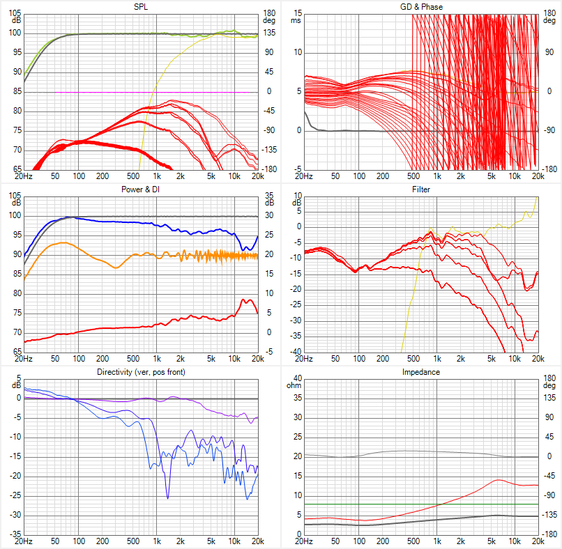
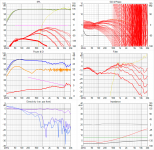
Based on my listening distance, the ceiling reflection occurs at about 45 degrees of axis and the floor reflection at about 30 degrees of axis. Standing up is about 15 degrees off axis. So I am trying hard to get that 15 degree response as close to on axis as possible and at the same time suppress the response at 30 and 45 degrees as much as possible.
I would say I am at least partially successful here. 30 and 45 degree output is down quite a bit and the reflections are not very prominent. It is very hard to get a flat response at 15 degrees and I would like to get it better. The little extra network for the driver group 3-4 helps a little bit but there is still a long way to go (not sure how much there is to be done tough). I would also like to get a more narrow response from 1 kHz and downwards.
Then, as I wrote earlier, I will try to use absorbents close to the baffle to get a narrower and more uniform horizontal response. The Beyma gets very directive above 10 kHz and I would like a more smooth transition to this.
Now groups of 4 driver with only 2 in the centre group (attenuated with resistors to match the response with the other groups).
Response like this:
Based on my listening distance, the ceiling reflection occurs at about 45 degrees of axis and the floor reflection at about 30 degrees of axis. Standing up is about 15 degrees off axis. So I am trying hard to get that 15 degree response as close to on axis as possible and at the same time suppress the response at 30 and 45 degrees as much as possible.
I would say I am at least partially successful here. 30 and 45 degree output is down quite a bit and the reflections are not very prominent. It is very hard to get a flat response at 15 degrees and I would like to get it better. The little extra network for the driver group 3-4 helps a little bit but there is still a long way to go (not sure how much there is to be done tough). I would also like to get a more narrow response from 1 kHz and downwards.
Then, as I wrote earlier, I will try to use absorbents close to the baffle to get a narrower and more uniform horizontal response. The Beyma gets very directive above 10 kHz and I would like a more smooth transition to this.
Attachments

Further testing shows that some phase tricks in the FIR-filter for the tweeter can be used to raise the response at +15 degrees:
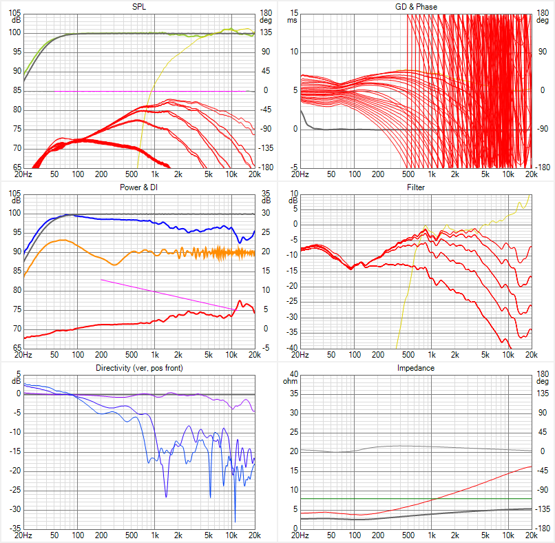
Seems that it comes with the cost of a slightly higher output at 30 and 45 degrees tough. So many parameters to tweak...
Seems that it comes with the cost of a slightly higher output at 30 and 45 degrees tough. So many parameters to tweak...
Attachments
Had the opportunity to do some measurements today.
Tried different positions and different absorption alternatives.
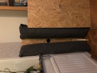
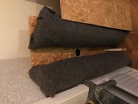
The best option so far looks like this:
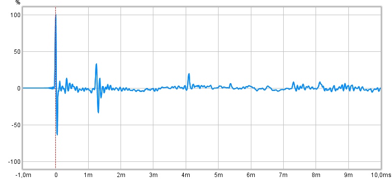
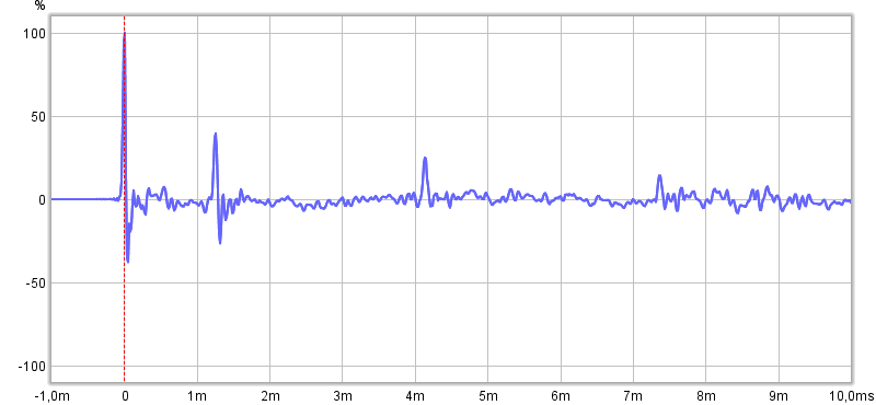
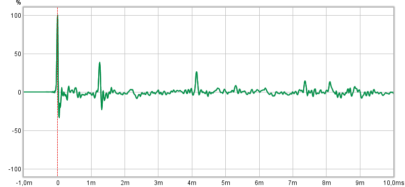
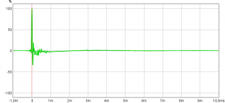
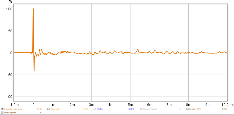
Impulse response at listening position:

Tried hard to get the first 1 ms clean but I believe more could be done here. Both the baffle and absorbents are a bit crude and the transition between the baffle and absorbents could be better. I will experiment more with this.
Peaks at 1.25 and 4.1 ms is floor and ceiling reflections and would probably not be of concern here. The peak at 5.35 ms is the reflection from the opposite wall. I tried to put some absorption there as well and could reduce it a bit:
(I sort of got an approval for having an absorption panel there...)
On the other wall I have the big window so I need to get as heavy curtains as allowed to reduce that one.
The peaks at 7,3 ms and 8,1 ms has yet to be identified, not sure where they come from. There is a beam in the ceiling between this part of the room and the other part and I suspect this could be an explanation. In that case this will also be of less concern with the arrays.
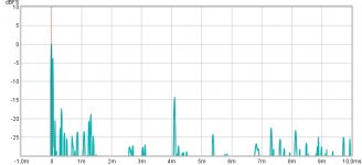
Except for the floor and ceiling, and the things happening very early (about 330 us) reflection are well below -20 dB:
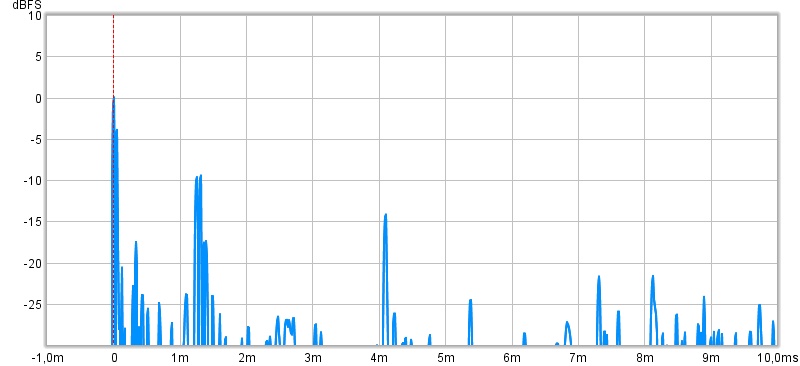
One thing that I don't really understand: look at the peak that I identified as floor bounce here (about 1.3 ms). There are actually four closely spaced peaks there. If I put a lot of pillows etc. on the floor half way between the speaker and microphone they are all reduced, so it can only be the floor:

Just curious since the ceiling peak is just one peak and nothing more. It should be causing any problems anyway with the array.
Tried different positions and different absorption alternatives.
The best option so far looks like this:
Impulse response at listening position:
Tried hard to get the first 1 ms clean but I believe more could be done here. Both the baffle and absorbents are a bit crude and the transition between the baffle and absorbents could be better. I will experiment more with this.
Peaks at 1.25 and 4.1 ms is floor and ceiling reflections and would probably not be of concern here. The peak at 5.35 ms is the reflection from the opposite wall. I tried to put some absorption there as well and could reduce it a bit:
(I sort of got an approval for having an absorption panel there...
)On the other wall I have the big window so I need to get as heavy curtains as allowed to reduce that one.
The peaks at 7,3 ms and 8,1 ms has yet to be identified, not sure where they come from. There is a beam in the ceiling between this part of the room and the other part and I suspect this could be an explanation. In that case this will also be of less concern with the arrays.
Except for the floor and ceiling, and the things happening very early (about 330 us) reflection are well below -20 dB:
One thing that I don't really understand: look at the peak that I identified as floor bounce here (about 1.3 ms). There are actually four closely spaced peaks there
. If I put a lot of pillows etc. on the floor half way between the speaker and microphone they are all reduced, so it can only be the floor:Just curious since the ceiling peak is just one peak and nothing more. It should be causing any problems anyway with the array.
Attachments
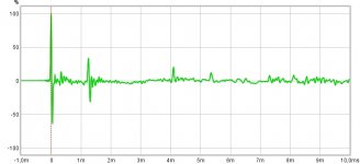

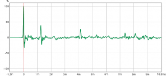
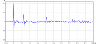
Yes, here is a comparison:
With right panel:
Without it:
Not that much difference in the early response. Biggest difference is that the peak at 8.1 ms gets less prominent. I have still some furniture and stuff (two big boxes of Vifa:s) in the room that won't be there later, so maybe it can be the cause of that peak. I will move away all other stuff before the next set of measurements.
My biggest concern just now is the first millisecond and I would like it to be cleaner. There is a peak at 330 us that I don't seem to get rid of in any of my different tries yet...
With right panel:
Without it:
Not that much difference in the early response. Biggest difference is that the peak at 8.1 ms gets less prominent. I have still some furniture and stuff (two big boxes of Vifa:s
) in the room that won't be there later, so maybe it can be the cause of that peak. I will move away all other stuff before the next set of measurements.My biggest concern just now is the first millisecond and I would like it to be cleaner. There is a peak at 330 us that I don't seem to get rid of in any of my different tries yet...
Attachments
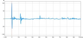
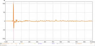
Hmm, pulled the speaker out into the room and measured the response without anything disturbing it:

That 330 us peak is still there!
A nearfield measurement of the driver shows this:


Not that clean in the first 500 us! Is this expected?
That 330 us peak is still there!
A nearfield measurement of the driver shows this:
Not that clean in the first 500 us! Is this expected?
Attachments
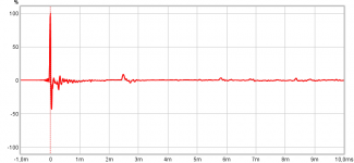
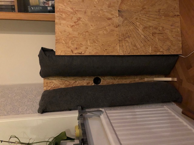
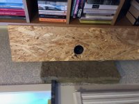
It is very hard to avoid anything that can cause the response to be messy in that time frame. Maybe look at your microphone mounting and how the driver is mounted to the chipboard. Looks in the picture to not be flush.Not that clean in the first 500 us! Is this expected?
Looks like baffle edge/absorber junctionAbout 115 mm - what have you got there?
//
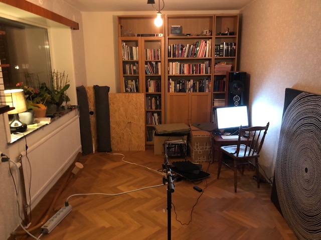
More measurements today. With a setup looking like this:
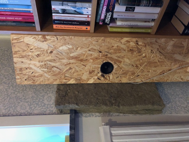
Measurement at the listening position about 2,9 meters from the speaker and then moving the mic 10 cm increments to the left or up from this position. This helps me to understand the direction of the reflections in the impulse response.
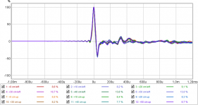
That 300 us peak has been annoying. If I compare all measurement for the first millisecond it looks like this:
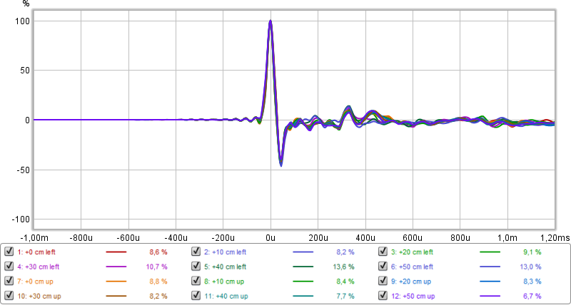
The peak is there for all measurement positions. The good thing with this is that it could be fixed using the FIR filter.
Looking at how the impulse response differs with vertical mic position:

Peaks that aren't moving much would be due to reflections on vertical surfaces (walls and other parallel planes to the array) while peaks that clearly moves would be due to reflections in horizontal surfaces (floor, ceiling). Every peak that moves should therefore be of less concern with the complete array.
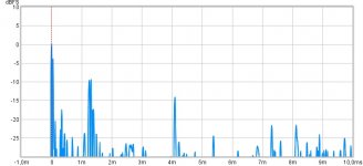
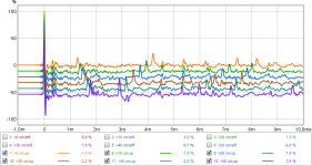
A vector average of the impulse for different vertical positions shows the most problematic peaks:
5.4 ms is the reflection of the opposite wall. I have put some absorption there (an old panel of 4.5 cm rockwool), but I would like to reduce it further. There is also the one at 436 us which I believe is the near wall reflection. Here I have 2 sheets of 4.5 cm rockwool at the moment. There more I move the mic to the left, the weaker it gets. When moving the speaker to be in line with the book shelf and toeing in a bit as in the first picture there isn't space for more than 12 cm wide absorption panel because of the window. Therefore I think that the first wall reflection "misses" the absorption panel from the reference position point of view. Two ways to fix this: moving the speaker closer to the wall or move the speaker back (but then it can't be in line with the shelf anymore). I will keep om experimenting.
Measurement at the listening position about 2,9 meters from the speaker and then moving the mic 10 cm increments to the left or up from this position. This helps me to understand the direction of the reflections in the impulse response.
That 300 us peak has been annoying. If I compare all measurement for the first millisecond it looks like this:
The peak is there for all measurement positions. The good thing with this is that it could be fixed using the FIR filter.
Looking at how the impulse response differs with vertical mic position:
Peaks that aren't moving much would be due to reflections on vertical surfaces (walls and other parallel planes to the array) while peaks that clearly moves would be due to reflections in horizontal surfaces (floor, ceiling). Every peak that moves should therefore be of less concern with the complete array.
A vector average of the impulse for different vertical positions shows the most problematic peaks:
5.4 ms is the reflection of the opposite wall. I have put some absorption there (an old panel of 4.5 cm rockwool), but I would like to reduce it further. There is also the one at 436 us which I believe is the near wall reflection. Here I have 2 sheets of 4.5 cm rockwool at the moment. There more I move the mic to the left, the weaker it gets. When moving the speaker to be in line with the book shelf and toeing in a bit as in the first picture there isn't space for more than 12 cm wide absorption panel because of the window. Therefore I think that the first wall reflection "misses" the absorption panel from the reference position point of view. Two ways to fix this: moving the speaker closer to the wall or move the speaker back (but then it can't be in line with the shelf anymore). I will keep om experimenting.
Attachments
Thanks nc535. Yes I believe some real good results are possible to get out from this project.
The closer I could get the speaker into the corner, the earlier in time the reflection would be and moving interference higher up in frequency. I'll continue my investigations and post the results here.
The closer I could get the speaker into the corner, the earlier in time the reflection would be and moving interference higher up in frequency. I'll continue my investigations and post the results here.
Looking back in this thread and can’t really give up the idea of a horn like the one Joseph proposed. Maybe like this and putting subs below and on top:
What do you think?
Only 16 Tc9:s left but I figure I would still be able to control the vertical directivity. The outer ones were cut pretty low in my earlier Vituix sims anyway.
The horizontal directivity however...I don’t have the knowledge/experience with horns to really understand their behavior or do reliable simulations. A bit worried what happens where the horn and wall meet.
Attachments

All I'd advise is not to have abrubt endings of the horn. I'd never use such a sharp edge, as that edge most probbably leads to diffraction plus it is something all the drivers have in common. (same distance to that sharp edge)
As I've mentioned more than once, avoid parallel ridges and planes. Unless you can make it a seamless transition. Whatever the drivers have in common (regarding to distances) will not be averaged by the (use of) multiple drivers. Yet that averaging is one of the strong points of an array. At least in my humble opinion.
As I've mentioned more than once, avoid parallel ridges and planes. Unless you can make it a seamless transition. Whatever the drivers have in common (regarding to distances) will not be averaged by the (use of) multiple drivers. Yet that averaging is one of the strong points of an array. At least in my humble opinion.
Last edited:
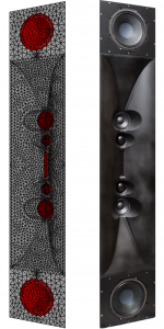
Have you see this construction from Follgott the Aries M, uses a TPL 150Looking back in this thread and can’t really give up the idea of a horn like the one Joseph proposed. Maybe like this and putting subs below and on top:
Aries M Dokumentation - PDF Free Download
Attachments
- Status
- This old topic is closed. If you want to reopen this topic, contact a moderator using the "Report Post" button.
- Home
- Loudspeakers
- Full Range
- Another corner line array, 28 TC9FD18