Hi there!
After moving to a new house I decided to build a new set of speakers. My wife had been complaining on the previously somewhat bulky speakers and I was therefore planning on something that didn't need to take up so much floor space and could be placed into the corners of the room. My thought was going in the direction of a full range line array so I started to look for inspiration. Soon I found wesayso's gigantic thread on this forum, and this has been a main inspiration for this project.
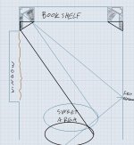
My plan is to build a big bookshelf, covering most of the wall and integrate the speakers on the sides. The room width is about 2.8 meters and the listening area will be about 3 meters from the wall. As of now, the room looks like this:

Ceiling height is about 2.5 meters, so there is room for 28 TC9FD18 drivers on each side. 4 sections in series with 7 drivers each in parallell should do. Minimum driver impedance is 7.75 ohms, so the resulting impedance would be 4.4 ohms.
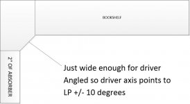
As can be seen in the photo, there is a big window on the left. The first reflection point from the right speaker will be right on this window. No chance of stuffing the window with absorption...so I got this idea of trying to absorb the sound close to the speaker instead. By doing so I want to narrow the horizontal dispersion and avoid any early reflections in the listening spot:

It would look something like this:

The plan so far is to build four separate cabinets for each side, containing 7 drivers each, and stack them. 2.5 liters internal volume per driver and 16 mm thick MDF for cabinet walls. Drivers front mounted and then (a better looking) second baffle made of oak attached on top of that. One section would look like this:

This is the plan for now, but I'm sure some things will change in the process.") 70 drivers (some for future ideas, like ambience speakers etc.) ordered and are on the way!
70 drivers (some for future ideas, like ambience speakers etc.) ordered and are on the way!
After moving to a new house I decided to build a new set of speakers. My wife had been complaining on the previously somewhat bulky speakers and I was therefore planning on something that didn't need to take up so much floor space and could be placed into the corners of the room. My thought was going in the direction of a full range line array so I started to look for inspiration. Soon I found wesayso's gigantic thread on this forum, and this has been a main inspiration for this project.
My plan is to build a big bookshelf, covering most of the wall and integrate the speakers on the sides. The room width is about 2.8 meters and the listening area will be about 3 meters from the wall. As of now, the room looks like this:
Ceiling height is about 2.5 meters, so there is room for 28 TC9FD18 drivers on each side. 4 sections in series with 7 drivers each in parallell should do. Minimum driver impedance is 7.75 ohms, so the resulting impedance would be 4.4 ohms.
As can be seen in the photo, there is a big window on the left. The first reflection point from the right speaker will be right on this window. No chance of stuffing the window with absorption...so I got this idea of trying to absorb the sound close to the speaker instead. By doing so I want to narrow the horizontal dispersion and avoid any early reflections in the listening spot:
It would look something like this:
The plan so far is to build four separate cabinets for each side, containing 7 drivers each, and stack them. 2.5 liters internal volume per driver and 16 mm thick MDF for cabinet walls. Drivers front mounted and then (a better looking) second baffle made of oak attached on top of that. One section would look like this:
This is the plan for now, but I'm sure some things will change in the process.
70 drivers (some for future ideas, like ambience speakers etc.) ordered and are on the way!Original speakers look very nice, but the plan for the new lines integrates them better in your room.
The asymmetrical waveguide you have in front of the lines would benefit from some simulation to see what effect it will have.
Perhaps you could bring the line further to the front plane of the bookcase and make the waveguide symmetrical for a more predictable response.
The asymmetrical waveguide you have in front of the lines would benefit from some simulation to see what effect it will have.
Perhaps you could bring the line further to the front plane of the bookcase and make the waveguide symmetrical for a more predictable response.
The ends of these I would do so the meet the wall flush. Having a side like that odf 3-5 cm isn't going to do any good for diffraction.
https://www.diyaudio.com/forums/att...0627-corner-line-array-28-tc9fd18-sektion-jpg
//
https://www.diyaudio.com/forums/att...0627-corner-line-array-28-tc9fd18-sektion-jpg
//
Felt works almost like a baffle at most frequencies. Someone showed that here by building a baffle out of 1,5 cm felt that behaved almost identical to one made out of wood.
With your situation I would not have buried the lines into the corner like that given the bookshelf - rather, I would place them flush with the bookshelf trying to avoid that "horn"...
//
With your situation I would not have buried the lines into the corner like that given the bookshelf - rather, I would place them flush with the bookshelf trying to avoid that "horn"...
//
Attachments
Last edited:
You would have to test the rockwool and felt so see it's properties combined or try the multi layer porous absorber calculator.
Without the correct material and depth you are likely to create a frequency dependant absorber/reflector which is not good.
It shouldn't be too hard to build a waveguide in front of the line to steer the sound away from the trouble spots.
Without the correct material and depth you are likely to create a frequency dependant absorber/reflector which is not good.
It shouldn't be too hard to build a waveguide in front of the line to steer the sound away from the trouble spots.
Without simulation (or even with), your waveguide should be done on a small scale as a pathfinder. Maybe build a 4 tall unit and have a listen. Anytime you put something in front of a driver cone or near it within first few inches, it has to be smooth and free of edges and flat reflecting faces - especially at the transition from driver bezel to the flat horn. It’s very sensitive to there.
I also think it is safer to mount drivers flush in an extended box.
I also think it is safer to mount drivers flush in an extended box.
I see a lot of suggestions for a different placement etc. However, the waveguide, being made from absorbing materials might not be a bad idea.
I would build up one part as you drew up and take (lots of) measurements to learn what it does. If it really acts as a waveguide despite being absorbent there's still not much wrong with it in my opinion.
The thing I would focus on is how the early IR looks, does it show obvious early reflections? If not, if it's relatively clean in the very early, say 0-5 ms, window this would certainly deserve a shot.
I'd place that single module on a temporary stand placing it at about half way height to keep distance between floor and ceiling and measure it with the mic at center height. Measure it along the whole area of interest to see if it stays within reasonable values there.
Even packed tight in a corner that corner will be roughly within equal distance to all drivers in the array, as seen from the listening spot/area. So without absorbing that will still have an effect on the IR thus on the frequency response.
Simulations can be helpful, but in a case like this nothing would beat just mocking up something close to the real thing. It doesn't have to be pretty, just functional for the temporary experiment.
At least, that's what I would do. All other proposals have their strong and weak points too. This might not be a bad idea, if done right.
I hope you do plan on some serious EQ tools, as no doubt you'll need it. Tucked into a corner like that you should be able to get some bass out of it too.
With one warning though, the highly symmetrical left and right sides do mean that if one corner has a problem at a certain frequency, the other one probably suffers at the same range to. Some times a little less symmetry isn't a bad thing, especially down low in frequency.
Last edited:
Thank you all for your valuable comments. They make me think more about this.
One goal of this project is to really reduce the amount of early reflections in the listening area, so that is the reason for the absorbing "waveguides". I was thinking that the absorbers would "eat up" most of the sound waves in other directions than those aiming at the listening position. At least for higher frequencies (90 mm of this rock wool should absorb most of the sound above about 700 Hz according to the porous layer simulator if I interpret the values right). But then, I didn't think to much about diffraction - I simply believed that the absorber, being on the baffle so close to the driver, would take care of that.
I dont't have any means of doing such simulations I'm afraid. But as many of you suggested, I will make a some kind of "test"-cabinet and run some measurements in order to gain some more understanding of the diffraction effects. I searched the web and it seems that many already have experimented with absorbing material on the baffle in order to reduce diffraction with good results, so I still have good hopes on this.
Oh yes! There will be heavy eq:ing. I'm following your lead here wesayso, and will go the FIR route. Probably through JRiver. I hope the bass will be enough. As I remember from your thread, there was enough bass capacity in your arrays for music but maybe not for home theater (and now you have subwoofers). To be sure, I will design the bookshelf to accommodate more bass support if needed.
One goal of this project is to really reduce the amount of early reflections in the listening area, so that is the reason for the absorbing "waveguides". I was thinking that the absorbers would "eat up" most of the sound waves in other directions than those aiming at the listening position. At least for higher frequencies (90 mm of this rock wool should absorb most of the sound above about 700 Hz according to the porous layer simulator if I interpret the values right). But then, I didn't think to much about diffraction - I simply believed that the absorber, being on the baffle so close to the driver, would take care of that.
I dont't have any means of doing such simulations I'm afraid. But as many of you suggested, I will make a some kind of "test"-cabinet and run some measurements in order to gain some more understanding of the diffraction effects. I searched the web and it seems that many already have experimented with absorbing material on the baffle in order to reduce diffraction with good results, so I still have good hopes on this.
I hope you do plan on some serious EQ tools, as no doubt you'll need it. Tucked into a corner like that you should be able to get some bass out of it too.
Oh yes! There will be heavy eq:ing. I'm following your lead here wesayso, and will go the FIR route. Probably through JRiver. I hope the bass will be enough. As I remember from your thread, there was enough bass capacity in your arrays for music but maybe not for home theater (and now you have subwoofers). To be sure, I will design the bookshelf to accommodate more bass support if needed.
Always fun when someone starts a new array project.
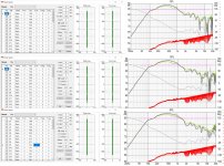
I modelled a modular line array the other day. I modelled 1.5" gaps in a line of 1.5" drivers because that was easy. Of course 1.5" is worse than it would be but I wanted a quick answer as to whether gaps at module boundary would hurt the HF response. Below graphs show the line's simulated response with and without the gaps. Modularity doesn't come without a cost.
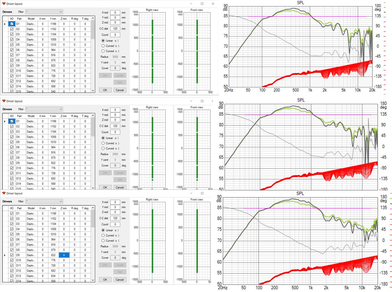
I modelled a modular line array the other day. I modelled 1.5" gaps in a line of 1.5" drivers because that was easy. Of course 1.5" is worse than it would be but I wanted a quick answer as to whether gaps at module boundary would hurt the HF response. Below graphs show the line's simulated response with and without the gaps. Modularity doesn't come without a cost.
Attachments
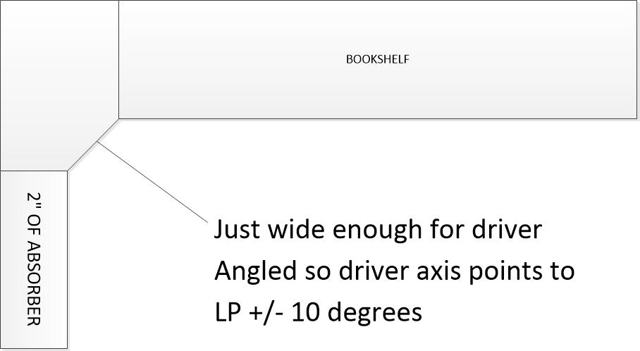
I'd also like to suggest an alternate bookshelf integration approach that pulls the driver out past the bookshelf so it gets to illuminate more of the room and doesn't have horn diffraction and mouth reflection issues. You might need to fill the ends of the bookshelf with large books or absorber for best performance. The absorber on the other side of the drivers eliminates an early reflection from where the angled baffle would meet the wall
Attachments
If the material is absorbent enough it should have control over the polar response in the same way that a dipole does through cancellation, not a waveguide in the strictest sense but does much the same thing in practice. If the absorption is broadband enough it should be good. My concern would be to make sure it is broadband enough as close to transition as possible and the asymmetrical nature of it. Asymmetrical waveguides introduce pattern flip which being polar related can't be EQ'd away. This is not so bad in the vertical but in the horizontal it is undesirable, you don't see very many horizontally asymmetrical waveguides for good reason.If it really acts as a waveguide despite being absorbent there's still not much wrong with it in my opinion.
I agree that the basic idea is good. You may have chosen rockwool because it is rigid? Rockwool is very dense and it often has a downtilting absorption rate which gets worse the more dense it is. Fibreglass is usually better but it needs to be thicker.One goal of this project is to really reduce the amount of early reflections in the listening area, so that is the reason for the absorbing "waveguides". I was thinking that the absorbers would "eat up" most of the sound waves in other directions than those aiming at the listening position. At least for higher frequencies (90 mm of this rock wool should absorb most of the sound above about 700 Hz according to the porous layer simulator if I interpret the values right). But then, I didn't think to much about diffraction - I simply believed that the absorber, being on the baffle so close to the driver, would take care of that.
If you already have the rockwool and felt then experimenting in practice is the way to go, but if you don't then playing with some numbers in a calculator might be useful
I see I'm not the only one doesn't think the driver should be recessed so as to create a horn. I see consensus for absorber on the side wall. Can we predict the effect of the absorber on the bookshelf side of the horn?
I don't know what the scale is but I guesstimate that is a 2 to 3" thickness of absorber. I'll grant that will be almost wholly effective above 1 khz or so and partially effective below. So lower midrange frequencies may be diffracting of the bookshelf corner only 3 or 6 or 9 db down through that range, increasingly attenuated with frequency. That could be problematic. You not only have a very early reflection from that corner out to the LP but you have a scattering of sound off that corner towards the side walls, albeit somewhat attenuated. That affects the power response and probably detracts from imaging. At least that is my concern...
I've also thought about placing a line of full range drivers at the apex of a V or in a corner. Absorbers on adjacent sidewall is key to making this work. Without absorbers you get reflections from where the angled baffle meets the sidewall. The path length difference for these reflection is the distance from the driver center to the wall. At the frequency where this distance is half a wavelength, you would get a reflection null. You need great enough absorber thickness there to limit null depth to where you have enough headroom to equalize it, at least 6 db, ideally 10 db.
When you rotate one side wall as you propose to get past the bookshelf corner, can you get both enough absorber and wide enough angle direct beam coverage? That, along with the issues I brought up in my first paragraph is what you need to judge or test via prototype.
If you bring the angled baffle out to where it meets the bookshelf corner as I drew, these concerns go away and all you have to worry about is how much of your bookshelf needs to be filled with absorber to preclude boundary issues from that side.
Thank you all for the input and suggestions! I will not rule out the “absorbing wave guide” just yet. I imagine that it could be beneficial to greatly reduce any reflected/diffracted sound from the front half of the room and increase the direct-to-reflected sound ratio. I have read in more than a few places about the benefit to reduce the early reflections (until the Haas effect onset).
But I clearly need to do some measurements in order to understand how the waveguide works in terms of diffraction etc. If it proofs to be a problem then I will consider moving the speakers forward as many of you suggested.
Nc535: Interesting simulations. I didn’t plan to have any excess space between the sections, so the top/bottom of the sections need to be max 4 mm each in order to keep the driver distance that small. The more I think of it, the more I am leaning towards another box design. Maybe a stacked one like wesaso’s. I have a friend with a CNC router...
Fluid and nc535: Thanks for the suggestion, I will try fiberglass as well. The idea is to have enough absorption in order to attenuate sound down to at least some hundred Hz. Below that the wavelength would be long enough so that the reflected sound from the waveguide would be practically in phase with the direct sound in the listening area. In the sketch from the first post the absorber on the left side is 90 mm thick.

Drivers arrived yesterday! I will keep you updated with measurements any time soon!
But I clearly need to do some measurements in order to understand how the waveguide works in terms of diffraction etc. If it proofs to be a problem then I will consider moving the speakers forward as many of you suggested.
Nc535: Interesting simulations. I didn’t plan to have any excess space between the sections, so the top/bottom of the sections need to be max 4 mm each in order to keep the driver distance that small. The more I think of it, the more I am leaning towards another box design. Maybe a stacked one like wesaso’s. I have a friend with a CNC router...
Fluid and nc535: Thanks for the suggestion, I will try fiberglass as well. The idea is to have enough absorption in order to attenuate sound down to at least some hundred Hz. Below that the wavelength would be long enough so that the reflected sound from the waveguide would be practically in phase with the direct sound in the listening area. In the sketch from the first post the absorber on the left side is 90 mm thick.
Drivers arrived yesterday!
I will keep you updated with measurements any time soon!Can hardly wait to see something, but do take your time. Indeed it would be good to have the drivers from different sections as close together as possible. As my thread demonstrated large stacks aren't without some drawbacks of their own
I was just reviewing the first couple of pages in your thread...
I should avoid gluing the rods - Status
- This old topic is closed. If you want to reopen this topic, contact a moderator using the "Report Post" button.
- Home
- Loudspeakers
- Full Range
- Another corner line array, 28 TC9FD18