Hi all! Thanks ahead of time for any advice you have - I've lurked here for quite a while but don't get around to posting much.
I've set about to design and build a pair of tiny (1" drivers) ported Fullrange speakers to sit on my desk. Space is very limited so they have to be small enough to sit underneath my monitors, and I'll be listening from 2-3 feet away. To this end I've been designing an enclosure which I'll be 3D printing as part of a project for an additive manufacturing class I'm taking. Since I'll only get one shot to print them and I won't have a ton of room for tweaking when they're finished, I'm hoping to get some suggestions/advice/critique on my current design before I move forward with buying drivers and building. I'm trying to apply all the best practices I can learn, but this is my first time designing enclosures
I think I've decided on Tang Band W1-1815SA Drivers (datasheet here) which have a fairly low Fs of 170 Hz and won't break the bank.
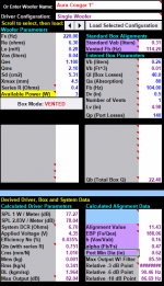
I've been using Jeff Bagby's "Woofer Box Model and Circuit Designer" calculator, which suggests a Vab of 0.12 L. Currently, my enclosure internal volume, minus port and driver volume, stands at 0.16 L. I'll either leave it be here or most likely take up some of that volume with some poly fill or weights after it's built.
Here are the calculations I've done. Looks like I'll end up with an F3 of around 100 Hz, which is better than I was hoping for. Not sure why F3 frequency is showing up as ##### though, maybe someone can enlighten me.

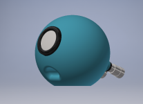
As it stands, everything assembled will look something like this. (Cyclops?? Maybe I'll paint them yellow and call them The Minions )
)

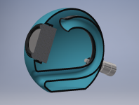
And the cutaway internal view:

I haven't been able to find many tiny ported speaker builds like this, so I would love some feedback. I'm not even completely confident I've done the calculations correctly! Particularly interested to hear what people think of the volume and whether I should be filling with some amount of damping. Could texturing the internal walls have any beneficial effect?
Thanks everyone, can't wait to build these lil guys!
I've set about to design and build a pair of tiny (1" drivers) ported Fullrange speakers to sit on my desk. Space is very limited so they have to be small enough to sit underneath my monitors, and I'll be listening from 2-3 feet away. To this end I've been designing an enclosure which I'll be 3D printing as part of a project for an additive manufacturing class I'm taking. Since I'll only get one shot to print them and I won't have a ton of room for tweaking when they're finished, I'm hoping to get some suggestions/advice/critique on my current design before I move forward with buying drivers and building. I'm trying to apply all the best practices I can learn, but this is my first time designing enclosures
I think I've decided on Tang Band W1-1815SA Drivers (datasheet here) which have a fairly low Fs of 170 Hz and won't break the bank.
I've been using Jeff Bagby's "Woofer Box Model and Circuit Designer" calculator, which suggests a Vab of 0.12 L. Currently, my enclosure internal volume, minus port and driver volume, stands at 0.16 L. I'll either leave it be here or most likely take up some of that volume with some poly fill or weights after it's built.
Here are the calculations I've done. Looks like I'll end up with an F3 of around 100 Hz, which is better than I was hoping for. Not sure why F3 frequency is showing up as ##### though, maybe someone can enlighten me.
As it stands, everything assembled will look something like this. (Cyclops?? Maybe I'll paint them yellow and call them The Minions
)
And the cutaway internal view:
I haven't been able to find many tiny ported speaker builds like this, so I would love some feedback. I'm not even completely confident I've done the calculations correctly! Particularly interested to hear what people think of the volume and whether I should be filling with some amount of damping. Could texturing the internal walls have any beneficial effect?
Thanks everyone, can't wait to build these lil guys!
Last edited:
I often build very small speakers like you have described. Getting any low end, even near field, is difficult of course. I have not used the W1-1815SA, but according to BassBox, you'll exceed Xmax at 100 hz at just over 1 watt.
+1 for the TEBM35. I've had fun with this driver.
Also, maybe the 1" Aura whisper (NSW1) could fit the bill. Higher Fs but with much more xmax to work with.
A cheapo that I've always been pleased with is the CE46P from Dayton. Maybe too big for what you are looking for. Another is the Peerless TC5FC07-04 that I also enjoy.
F3 is showing as "####" because the value is more than 2 digits plus 2 D.P. long. I.e. because it is greater than 99.99Hz
Thanks! Not surprised that this spreadsheet wasn't expecting any 3-digit F3 numbers
If you can go a bit up in size, maybe you could try to have a look at the BMR TEBM35. These sound quite good in a small 3D printed box.
I often build very small speakers like you have described. Getting any low end, even near field, is difficult of course. I have not used the W1-1815SA, but according to BassBox, you'll exceed Xmax at 100 hz at just over 1 watt.
+1 for the TEBM35. I've had fun with this driver.
Also, maybe the 1" Aura whisper (NSW1) could fit the bill. Higher Fs but with much more xmax to work with.
A cheapo that I've always been pleased with is the CE46P from Dayton. Maybe too big for what you are looking for. Another is the Peerless TC5FC07-04 that I also enjoy.
Thanks for the suggestions. I actually was looking at the NSW1 (Aura Cougar), then abandoned it when I found the Tang Band with a much lower Fs. I'll revisit the NSW1 and see what I can get from it. I haven't thought about exceeding xmax. Is there a free program which will show me that information?
I'll have a look at those other drivers as well, particularly the TEBM35 and TC5FC07. What size enclosure have you guys successfully used with these? I assume sealed? I'm fairly limited in volume, both by the room on my desk but also by the amount of material I'm allowed to use on the 3D printer
Check out this thread Ambience tweeters using small BMR drivers
I use the 3D printed boxes full of polyfil. While testing, the sound was surprisingly good and as full range as a small speaker can be.
I use the 3D printed boxes full of polyfil. While testing, the sound was surprisingly good and as full range as a small speaker can be.
Did a little more playing with Jef Bagby's calculator today, and spent a couple hours playing with a new enclosure design in Inventor.
Discovered that Jeff's calculator does in fact show xmax information. It too was showing way over xmax for the Tang Band at 100 Hz / 1W.
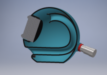
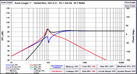
Messed with calculations for a couple of the larger (if you can call 2" larger ) drivers, and to me it looks like for a decent f3 of 100 Hz or so they want much larger enclosures than I'm willing to give them, sealed or ported. Maybe I'm doing something wrong... but for now decided to spend some more time with the Aura Cougar. Discovered that the xmax is no longer a problem but the 1/4" diameter port was wayyy too small. Port velocity was literally off the charts. So I squeezed a few more mL of volume from the enclosure and increased the port to (equivalent to) 1/2" diameter. This results in a peak port velocity of 40 m/s which I *guess* is okaaaay? I hesitate to go any larger.
Enclosure volume now sits at roughly 0.26 L, with a 5.0" long port. Going to have to wait for drivers and wire terminals to come in the mail to get it exact, as it seems like at this scale every mL makes a difference. Or I'm just thinking about it too hard
Anyway, here are a few pics with the new enclosure arrangement and some calculation results. I think I'll go ahead and order these drivers and see what happens.
Discovered that Jeff's calculator does in fact show xmax information. It too was showing way over xmax for the Tang Band at 100 Hz / 1W.
Messed with calculations for a couple of the larger (if you can call 2" larger
) drivers, and to me it looks like for a decent f3 of 100 Hz or so they want much larger enclosures than I'm willing to give them, sealed or ported. Maybe I'm doing something wrong... but for now decided to spend some more time with the Aura Cougar. Discovered that the xmax is no longer a problem but the 1/4" diameter port was wayyy too small. Port velocity was literally off the charts. So I squeezed a few more mL of volume from the enclosure and increased the port to (equivalent to) 1/2" diameter. This results in a peak port velocity of 40 m/s which I *guess* is okaaaay? I hesitate to go any larger.Enclosure volume now sits at roughly 0.26 L, with a 5.0" long port. Going to have to wait for drivers and wire terminals to come in the mail to get it exact, as it seems like at this scale every mL makes a difference. Or I'm just thinking about it too hard
Anyway, here are a few pics with the new enclosure arrangement and some calculation results. I think I'll go ahead and order these drivers and see what happens.
Attachments
On a scale like this, as you note, every cc counts.
FWIW I have experimented with slightly larger drivers, at 2", primarily tangband W2 800SL, but also Visaton FRS5X.
This tangband has Fs of 160Hz or so, and low Qts, and thus for a mid tweeter application, in a sealed volume, I calculated something like 55cc internal volume.
Due to the low Qts and highish Fs, these wont do bass, but the principle is the same.
I ran the drivers in small cuboid tealight holders, that were the correct volume, plus a few cc for the driver chassis displacement.
WinISD is a free program that will allow you to simulate both sealed and vented designs, once you've inputed your driver TS parameters.
You'll see in WinISD that the higher Qts of the Tangband 1" will pull the F3 point down a little below Fs in a vented cab, but it will be very finicky about vent length and cab volume, as well as driver tolerances.
E.g. if Qts is higher than spec sheet (usually the case IME) then volume and or vent length will become more difficult to accommodate inside the cabinet. This can be designed for, of course, but with a Qts approaching 0.7, then things reach a point where although bass output is increased, it may be lumpy, peaked, and hungover with larger group delay at LF
Last edited:
I'd also suggest that you download the FRD Consortium collection of software, which you can use to extract FRD and ZMA data from manufacture data sheets.
Then I'd suggest downloading Boxsim (or other simulator) and import these FRD and ZMA files for your TB driver, to simulate the acoustic output.
The reason I say this, is that due to the tiny baffle dimensions, you'll lose a large proportion of any bass you generate, due to baffle step losses (and compensation for this isnt likely possible, given the low efficiency, and fact you'll already be close to excursion limits at very low SPLs.
You'll probably find you're unlikely to get much output below 500Hz or so, due to the baffle loss, and certainly not the bass response that a single enclosure calculator will spit out.
Interesting, thanks. Dowloading WinISD and Boxsim as we speak!
I just did a bit of reading about baffle step losses and compensation (here and here)
Am I somewhat helped by the fact that my speakers will be backed up fairly close to a wall behind them? I understand that this placement has drawbacks of it's own but they do have to fit on my desk somehow
The calculator I'm using now suggests that I peak at about half of xmax at 85 dB, so maybe there is some leeway for some compensation? Will have to see what WinISD and Boxsim say. The plot thickens!
Wall placement will certainly help mitigate Baffle loss, but how much exactly would be difficult to determine without measuring in room response.
That's another story altogether, with room gain adding to output, again variable, depending on many factors.
If I were to attempt something of this type, I would be tempted to 3D print a compact hemispherical enclosure, that can be wall mounted.
An alternative would be to corner load the "pods" close to the walls, in each corner of the listening space. Then the drivers are radiating into 1Pi space (I think this is correct, I'm a bit rusty) rather than 2Pi space, and baffle losses are reduced. You may have more side reflections as a result though. You could even print a1/4 or 1/8th sphere section, so that the enclosure back fits neatly into a corner....
It's all an exercise in compromise
Then perhaps baffle loss becomes far less of a problem, since the wall and box are almost one thing (almost an Infinite Baffle)
Last edited:
@mattdog: I’m curious as to why you seem to have settled on a ported enclosure. Wouldn’t a sealed design get you closer to the size you want? Perhaps it has to do with your desired f3 but, regardless of enclosure type, you’re going to need a subwoofer for any hope of extended bass. A sealed enclosure would also be simpler to design/print and could be done in one piece as long as you weren’t using a rear-mount driver (like the Aura).
I’m not trying to dissuade you from your choices, it’s more curiosity on my part.
I’m not trying to dissuade you from your choices, it’s more curiosity on my part.
My primary reasoning, like you said, was getting some semblance of bass from these tiny drivers. Still not sure if I'll pull that off but we'll see. Might pair with a subwoofer later, but hitting 20 Hz isn't really the goal. I just want some decent desk speakers with a little punch. If I want big bass I'll move to the living room
Efficiency was a thought as well. These drivers only manage 70 - 80 dB efficiency to begin with, not sure what a sealed enclosure would do to them. I'm just following the general wisdom that ported enclosures are more efficient. Thought about doing a passive radiator but that doubles my cost. Meh.
Finally (but maybe most importantly?) I'm doing this to fulfill a class project requirement, so I have to justify using 3D printing (in this case a very nice/expensive stereolithography machine) in the first place. To that end, the more complicated the better! Lol
Sounds silly, but to put it a different way I want to see what limitations of small speakers I might be able to get around by no longer being limited by conventional construction techniques and simple-ish designs. We'll see how it goes, but that's what I'm writing in my report anyway, whether I'm successful or not
Not to dissuade you from your choices at all, but I tend to agree with the above; sealed may be easier to realise when on the bounds of, I'd guess, simulation limitations.
Perhaps a more complex solution: MTM arrangement, with two drivers as a 0.5 woofer, covering the BSC region, with a single driver sealed in the centre.
If complexity is the goal the 0.5 driver could be vented or even maybe be 4th order BP given the micro dimensions the TB would probably require. And all that is added print complexity.
E.g. a 4th order BP will usually have a fairly broad BW, at least compared to 6th order, but mid band resonance occur that limit the extent you can push them up in frequency. So sub duty mostly.
But being as the cab would be so small and could be very accurately printed, I'd hazard a guess that the resonances would also be higher and less of an problem for reproduction at 500Hz for example, compared with almost any other BP cab, just because of the dimensions involved.
Last edited:
And all that is added print complexity.
And 4x the cost?
I joke, but it does sound like an interesting idea. I don't have any experience with 4th order bandpass speakers, but I'll do a little reading to better understand what you mean.
In the meantime I took your advice and imported the Aura Cougar driver to boxsim using SPLTrace. If I'm understanding it correctly, I'm somewhat encouraged by the results. High frequencies will definitely need to be rolled back (probably with EQ) but other than that it looks ok. Correct me if I'm misinterpreting somehow. This is at an internal volume of about 0.28 L, with a port tuned at 115 Hz.
Attachments
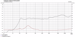
Well efficiency isnt great, bit you expected that.
The 10dB or so hump from 2k to 10k isnt so good, but could be dialled back with shelving EQ - that would probably leave the last octave attenuated somewhat.
Can I ask, are you sure your "cabinet" dimensions entered correctly into Boxsim?
I assume, that you used a similar sized driver loaded into Boxsim, and then imported frd and zma files? Cant see any Baffle Step at all (that is unless the Baffle step IS the rise from 2k onward)
Yes I was playing devils advocate with the suggestion of more drivers - although due to the miserable efficiency of this size of speaker, say 77dB@1m at 2W, then it isnt that crazy a suggestion.
For me at least, I'd like to achieve more than 80dB at the listening position. And I dont listen loud.
I had to somewhat fudge the dimensions of the cabinet since there's no option for a sphere. This is a baffle of 3 cm x 3 cm (and the diameter of the driver is about 2.6 cm so pretty close)
I used the SPLtrace software to create frd and zma files from the manufacturer datasheet of the Cougar driver, then imported those files to boxsim. Took a little bit of figuring out but I think it's set up correctly now. I assumed that the rise above 2k was indeed the baffle step effect, since I learned that a spherical enclosure should show a smooth increase of 6 db from low to high frequency, which this seems to show, but there is a small bump above 2k on the datasheet for the driver as well.
I agree the SPL even at listening range leaves something to be desired. I adjusted the listening distance to 70 cm from 100 cm (splitting hairs here but it is more accurate) and it helped a bit (inverse square law in action I suppose). I'm hoping that placement and positioning near the wall might help a bit with that, which I don't think I'm able to simulate. I guess I could see what boxsim comes up with when I give the cabinet a very large baffle instead... Might give me a decent ballpark. Maybe I'll try that.
If imagine the rise due to baffle step would be much less intrusive, or less awkward, if you hung your enclosure on to the rear of something like a A4 sized curved or part spherical baffle.
That way youd hopefully keep a nice smooth baffle transition, but lower down, perhaps 500Hz, but better efficiency to that point.
Below about 500Hz, aside from a BSC filter, which would eat any headroom you had left, there isnt much you can do. Mount one driver in the middle of a door, and I suspect it would work a treat, still at very low SPL.
- Status
- This old topic is closed. If you want to reopen this topic, contact a moderator using the "Report Post" button.
- Home
- Loudspeakers
- Full Range
- Tiny 1" Ported Fullrange Project - Seeking Wisdom!