Hello to all
an update on the construction of the 34c9 speakers.
Thanks for the update. And thanks for sharing your innovative project(s). I'm tempted to try, but don't have the time (lots of drivers, though) right now. However, it does not seem overly complicated.....
It is very easy to build and the result is worth it. Here is mine: My 34c9 (omnidirectional full range with 3FE22) build
Interesting project! I had a similar idea but different length pipes for the back loaded horn.
The PANPIPE (Pentahorn) BLH Speaker
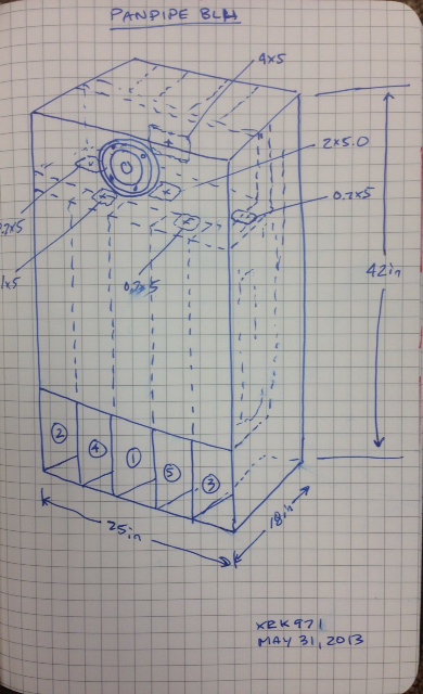
Unfortunately, I never got around to building it.
The PANPIPE (Pentahorn) BLH Speaker
Unfortunately, I never got around to building it.
Interesting project! I had a similar idea but different length pipes for the back loaded horn.
...
Unfortunately, I never got around to building it.
Hi xrk971
the PANPIPE speaker system (Pentahorn) BLH is much more complex to mount than the 34c9 project. The 34c9 has straight and side-by-side waveguides, which can be purchased ready at a hardware store.
I've already written it in other posts and I repeat: multiple wave guides have been used to optimize the omnidirectional emission (by diffraction) at all frequencies, coherent and delayed secondary sound waves described in MDD technology. The presence of waveguides of different lengths provides more options to adjust the response to low frequencies than a single path.
To this day I cannot say that MDD technology is certainly an innovation, and it improves the experience of listening to recorded music at home. It has been tried by very few people and it could be my ear that has become used to this effect. In order not to disappoint those who want to try to build an MDD project, I am studying options to regularize and extend the low frequency response with the 3fe25 loudspeaker. In any case (apart from MDD) the project of an omnidirectional and easy-to-build full-range is not trivial.
After this phase I will decide whether to do a Hi-End project or something else. I have no deadlines, no sales budget to respect. I go on for fun.
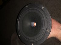
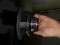
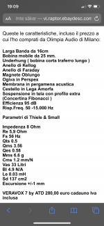
I would like to try and make a MDD for ATD Veravox 7 driver, it’s a 7” fullrange unit (italian make ��")
My wish is to mate it with a subwoofer so it only need to reach 80~150hz.
What model should I build? Can I expect the mids and highs to be as resolved as a direct radiator driver?
The woofer section Will be either tapped horn or dipole.
XO Will be active.
My wish is to mate it with a subwoofer so it only need to reach 80~150hz.
What model should I build? Can I expect the mids and highs to be as resolved as a direct radiator driver?
The woofer section Will be either tapped horn or dipole.
XO Will be active.
Based on my build, I would aim for the longest tube to be at ear level or slightly higher, the shortest is half of it and the rest logarithmically spaced. The easiest would be 7 tubes of a diameter close to 1/3 of the membrane diameter including the surround. I see no reason why this would not work. I use mine with a mono subwofer below ca 80 - 90 Hz.
Are the wave guides vertically directional? I wish to use just one Veravox 7 and feed it mono signal. My wish was for a fairly omnidirectional sound when seated and when I’m on my feet walking around.
How important is it that the drive unit is close to the floor, could I put the speaker on a stand to get the guides at the right level or would that ruin the design?
Of what imporance does the rear radiation of the drivar have in this design?
How important is it that the drive unit is close to the floor, could I put the speaker on a stand to get the guides at the right level or would that ruin the design?
Of what imporance does the rear radiation of the drivar have in this design?
Last edited:
The rear radiation is just another part of the source, as I see it - do not know how much the reflection from floor is adding to the output . Being close to the floor, it may enhance the bass a little, but with 1m max pipe array it is not much anyway (and that I expected). I am not at home to try out, but I think you can place them on a stand. The sound is omnidirectional horizontally, no question about that. But when you are standing, it feels kind of like you are watching the band from the top. The instrument placement is great in the horizontal plane, and it kind of feels like the plane is somewhere close to the longest tube. Imagine the band drawn on that plane and that is what you hear ('see') when you are standing. At a very close distance, this image kind of collapses - and further away, the effect is not so pronounced - I would say it depends on the angle between the plane and the line between the head and top of the speakers. That is with stereo. The "image" is very stable with a stable size - and it changes only in a way you would perceive a painting - e.g. things seem smaller from the distance - it is kind of hard to describe.
I am not sure how it would sound in mono, I have not tried that, since I finished the build, they are standing at the same place and I enjoy the "3D effect." If I have a chance, I will try to put them on stands and listen to one in mono.
The easiest way to try is to get some hard paper and build the paper version mentioned on Claudio's website - it will maybe take a long afternoon. I took the risk and used the Al tubes directly, the first trial was with the tubes connected with a doublesided tape and a temporary holder. It was immediately to be heard, that it is worth to finish these nicely. As I mentioned elsewere, my wife wished these were placed in the living room - first time I have ever heard that about any of my speakers )
I am not sure how it would sound in mono, I have not tried that, since I finished the build, they are standing at the same place and I enjoy the "3D effect." If I have a chance, I will try to put them on stands and listen to one in mono.
The easiest way to try is to get some hard paper and build the paper version mentioned on Claudio's website - it will maybe take a long afternoon. I took the risk and used the Al tubes directly, the first trial was with the tubes connected with a doublesided tape and a temporary holder. It was immediately to be heard, that it is worth to finish these nicely. As I mentioned elsewere, my wife wished these were placed in the living room - first time I have ever heard that about any of my speakers
)Hi PepeI would like to try and make a MDD for ATD Veravox 7 driver, it’s a 7” fullrange unit (italian make ��)
My wish is to mate it with a subwoofer so it only need to reach 80~150hz.
What model should I build? Can I expect the mids and highs to be as resolved as a direct radiator driver?
The woofer section Will be either tapped horn or dipole.
XO Will be active.
I have seen that you foresee the use of a sub, the following indications are for optimizing the reproduction of the high frequencies.
To get the high frequencies emitted by diffraction to the listener's ears, a compact version with wavelengths up to one meter long should be used as in projects 34C9, 22C7 and 66C9. I published a couple of drawings on the propagation of primary and secondary waves on the acoustic page.
The high efficiency 95 dB and the greater power compared to the 3FE25 driver require a structure that does not deform at high volume. The shape can be radial, circular, square or other. It must be strong enough to avoid non-linear deformations caused by the sound waves passing through them. Cardboard guides are only suitable for low-volume tests.
The diffraction at the end of a waveguide generates spherical fronts for all frequencies with wavelengths greater than the guide diameter. At 10 KHz the length is 3.4 cm, your Veravox 7 reaches 15 KHz which corresponds to 2.25 cm. In the prototypes I made, I used guides between 1 and 2.5 cm, actually I found the response up to 15 KHz off axis, the microphone resting on the source desk on the monitor and the speakers on the floor at the sides. I have not tried multiple large guides, 1/3 of the speaker diameter is about 5 cm. In guides with a diameter greater than 3 cm, the effect of diffraction can be increased with holes, slits or even an exponential profile as in the K-Tube trumpet in the final part of the guide. Another way to increase diffraction is to use a greater number of smaller waveguides, such as the 54M42 project. Multiple cell panels exist on the market that already have more waveguides side by side in alveolar polypropylene or even in polycarbonate.
Since you already have the Veravox 7 available I would mount them in a configuration optimized for low frequencies like the 21L7 project and I would add two small 3 "for the high unit in parallel. There would not be any diffraction problems at high frequencies and the need for an X-over would be eliminated.
Last edited:
Are the wave guides vertically directional? I wish to use just one Veravox 7 and feed it mono signal. My wish was for a fairly omnidirectional sound when seated and when I’m on my feet walking around.
How important is it that the drive unit is close to the floor, could I put the speaker on a stand to get the guides at the right level or would that ruin the design?
Of what imporance does the rear radiation of the drivar have in this design?
The guides are vertically directional downwards. If you place the diffraction holes at the height of the ears of a seated person, the high frequencies will feel good even when standing and walking.
If the loudspeakers are raised from the floor the diffraction holes will be positioned higher and the high frequency energy will be directed over the listener's head.
Rear radiation is the main radiation for low and medium frequencies. The driver near the walls strengthens the low and medium frequencies. On the contrary, raising the driver from the floor reduces the sound pressure of low and medium frequencies.
” Since you already have the Veravox 7 available I would mount them in a configuration optimized for low frequencies like the 21L7 project and I would add two small 3 "for the high unit in parallel. There would not be any diffraction problems at high frequencies and the need for an X-over would be eliminated”
@Claudiogan: Do you recommend this out of concern for the capability of the MDD scalability, 50mm pipe reproducing tweeter range with a 7” driver?
Found a store near me that sell 50mm rectangular pipes in aluminum. They allso sell 10, 20, 25, 30 & 40mm square alu tubes.
@Claudiogan: Do you recommend this out of concern for the capability of the MDD scalability, 50mm pipe reproducing tweeter range with a 7” driver?
Found a store near me that sell 50mm rectangular pipes in aluminum. They allso sell 10, 20, 25, 30 & 40mm square alu tubes.
Last edited:
@Claudiogan: Do you recommend this out of concern for the capability of the MDD scalability, 50mm pipe reproducing tweeter range with a 7” driver?
Found a store near me that sell 50mm rectangular pipes in aluminum. They allso sell 10, 20, 25, 30 & 40mm square alu tubes.
Hi Pepe
I have not yet made MDD prototypes with drivers with a diameter greater than 3" and the following considerations are hypotheses to verify with 6" drivers. Before switching to larger drivers, I still have a couple of configurations to check with the 3FE25 drivers.
The final section of each waveguide can be thought of as the surface of a flat tweeter facing upwards. At high frequencies (wavelength less than the diameter) increasing the diameter increases the fraction of energy sent towards the high and decreases the sound energy sent horizontally.
At diameters of 1, 2, 3, 4, 5 cm the frequencies 34.1, 17.1, 11.4, 8.5, 6.8 KHz correspond. Geometrically on a 16 cm cone, square matrices 3x3 x 5 cm, 4x4 x 4cm or 5x5 x 3 cm can be constructed. Even with seven 5 cm circular guides you can easily build an MDD load.
With smaller diameters, 1 or 2 cm the construction is complicated but there is an omnidirectional high frequency diffusion, already tested up to 15 KHz.
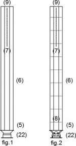
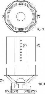
With large diameters the construction is simplified but there is the risk of attenuating the higher frequencies at the listening point, however the listening could be good due to the effect of coherent and delayed secondary waves. Your mono listening indication is special and I don't know how you will use the system. The horizontal emission can be increased by drilling holes in the final part of the free walls of the waveguides, fig.1 and fig.4. It could be enough 10 cm with 3 mm holes. The holes can be replaced by a line or a K-tube type profile.
If you want to experiment I recommend the use of PVC pipes for hydraulics or electrical systems, the material has low costs and is easily available.
If you want a system with a neat appearance and secure audio features you have to wait for the further development of the MDD technology.
Attachments
Last edited:
Claudio, if I wanted to scale up the number of waveguides within a certain range of Lmin and Lmax (for example, Lmin=20mm & Lmax=2000mm) beyond what you seem to be typically using (7-9 waveguides) how would that be calculated? Even in your 54M42 project you only mention 7 lengths (but I realize the alveolar polypropylene was supplied to you in joined sections). Several times you have stated: “The lengths are calculated with a logarithmic series to distribute them evenly over the entire octave” but I have yet to see the math. Is there a specific equation you are using and, if so, would you be willing to share it?
Claudio, if I wanted to scale up the number of waveguides within a certain range of Lmin and Lmax (for example, Lmin=20mm & Lmax=2000mm) beyond what you seem to be typically using (7-9 waveguides) how would that be calculated? Even in your 54M42 project you only mention 7 lengths (but I realize the alveolar polypropylene was supplied to you in joined sections). Several times you have stated: “The lengths are calculated with a logarithmic series to distribute them evenly over the entire octave” but I have yet to see the math. Is there a specific equation you are using and, if so, would you be willing to share it?
Hi CraigSu
to best reproduce the bass you don't have to use too different lengths on the same cone, the projects 21L7, 54M42, 34C9, 66C9 work well with Lmax = 2 * Lmin. If you shorten Lmin too much you will download the longest guides suitable for reproducing the lowest frequencies, working in parallel.
If the unit is optimized for high frequencies you can use the Lmax = 4 * Lmin ratio as in the 22C7 project.
In the 54m42 project the seven lengths refer to the corners of the oblique cut. The straight cut approximates the exponential fairly well over distances of a few centimeters. Each edge is used as a maximum of seven pipes and minimum of the next seven.
The formula for calculating lengths is already public, it is the formula for calculating the frequencies of musical notes, in an Excel-like style:
f = fr * POWER (2; i / 12) i = 0, ..., 12
replacing Lmax = Vsuond / fr the lengths are calculated
L = Lmax / POWER (2; i / N)
i = 0, ..., N-1 for an octave, N is the number of waveguides, i = N is not used as it is already in the following octave.
L = Lmax / POWER (2; i / N * 2)
i = 0, ..., N-1 for two octaves.
How about tilting the MDD slightly, think like Tower of Piza.
That way one could use longer guides (more guides) and avoid that the highs pass over your head (out of ”reach” of our ears).
One Could allso put the back/low part of the MDD in to a corner that will enhance the lows and lower mids.
What about that idea?
That way one could use longer guides (more guides) and avoid that the highs pass over your head (out of ”reach” of our ears).
One Could allso put the back/low part of the MDD in to a corner that will enhance the lows and lower mids.
What about that idea?
- Status
- This old topic is closed. If you want to reopen this topic, contact a moderator using the "Report Post" button.
- Home
- Loudspeakers
- Full Range
- 34c9 a MDD full range speakers.