Elleman, great idea! This could be a great way of constructing a larger one e.g. with 6 - 8" loudspeaker.
Edit: With the 3D printing - I wonder if the outer spiral could be made continuous and not in steps...and how would that work.
Yes if you have any ideas that would be aesthetically pleasing let me know and i can render it for you.
Elleman, great idea! This could be a great way of constructing a larger one e.g. with 6 - 8" loudspeaker.
Edit: With the 3D printing - I wonder if the outer spiral could be made continuous and not in steps...and how would that work.
It did not let me edit my previous post, but this is how i assume your idea would look like. The amount of "tubes" could be adjusted very easily, and i assume, still follow the correct logarithmic scale?
Attachments
Hi ellemanIt did not let me edit my previous post, but this is how i assume your idea would look like. The amount of "tubes" could be adjusted very easily, and i assume, still follow the correct logarithmic scale?
really very nice.
I have some questions.
Can you produce the standard file used in 3D printing centers?
Do you have a 3D printer and how fast would you make the various sections?
In the drawings did you keep in mind the fact that in the joints each inner radius must be glued airtight and without burrs? It is necessary to operate the wave guide with the total length.
In the next days I could send some configurations, with complete measurements.
It did not let me edit my previous post, but this is how i assume your idea would look like. The amount of "tubes" could be adjusted very easily, and i assume, still follow the correct logarithmic scale?
That looks really really good! One aesthetic thought I had was whether it would be possible to keep a smooth external profile, so that the joins between sections happen inside an outer layer and remain relatively invisible (if that makes sense). I guess this could be addressed by "dressing" the finished waveguide print with one external smooth tube.
I am one of those without a 3d printer, but would be very interested in getting at least one of these printed and build and measured.
Thanks for the nice words everyone!
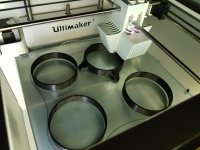
I started a print to test the joints. At the moment i have "quick" mode, which gives visible layers. Each layer is 0.2mm thick and the tube section with this settings would take about 8 hours, while the part which have all the tubes would take up to 23 hours. So a total print time of about 120 hours.
Going for a high quality print (layer height 0.15 and slightly slower movements) would probably double the printing time. The good thing is you set it up and it does the work on it's own. that means that i could start the print and with 4 sections at a time, it will be ready to be restarted with new sections about 3 days later, meaning i could make one complete column in a week. The material cost would be about 30€ per speaker. To cut cost and leadtime, one could make the print stick to a normal PVC tube for the fist 700mm, and save about 30h of print")
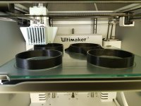
The joint will be air tight, it is made so that a flat surface will go bottom out on a flat surface. I want to test the joints so right now i am printing sections of about 40mm height just to see how it works. The pictures below are in the middle of the printing process.
The red picture below shows a crossection of the joint. Right now i have prioritized smoothness on the inside, leaving a visible joint on the outside. After some printing trails i should be able to make it invisible from the outside as well.
The goal is to be able to mount it air tight without glue. that would also make it alot easier to experiment with different heights.
When i have something that works i can share the STL files, which can be printed on any 3d-printer.
I do have a mini dsp with a microphone so i can do some measurements when it is done.
Please try to do a drawing on what you mean and i can try to do it
I started a print to test the joints. At the moment i have "quick" mode, which gives visible layers. Each layer is 0.2mm thick and the tube section with this settings would take about 8 hours, while the part which have all the tubes would take up to 23 hours. So a total print time of about 120 hours.
Going for a high quality print (layer height 0.15 and slightly slower movements) would probably double the printing time. The good thing is you set it up and it does the work on it's own. that means that i could start the print and with 4 sections at a time, it will be ready to be restarted with new sections about 3 days later, meaning i could make one complete column in a week. The material cost would be about 30€ per speaker. To cut cost and leadtime, one could make the print stick to a normal PVC tube for the fist 700mm, and save about 30h of print
The joint will be air tight, it is made so that a flat surface will go bottom out on a flat surface. I want to test the joints so right now i am printing sections of about 40mm height just to see how it works. The pictures below are in the middle of the printing process.
The red picture below shows a crossection of the joint. Right now i have prioritized smoothness on the inside, leaving a visible joint on the outside. After some printing trails i should be able to make it invisible from the outside as well.
The goal is to be able to mount it air tight without glue. that would also make it alot easier to experiment with different heights.
When i have something that works i can share the STL files, which can be printed on any 3d-printer.
I do have a mini dsp with a microphone so i can do some measurements when it is done.
That looks really really good! One aesthetic thought I had was whether it would be possible to keep a smooth external profile, so that the joins between sections happen inside an outer layer and remain relatively invisible (if that makes sense). I guess this could be addressed by "dressing" the finished waveguide print with one external smooth tube.
I am one of those without a 3d printer, but would be very interested in getting at least one of these printed and build and measured.
Please try to do a drawing on what you mean and i can try to do it
Attachments

You've already done it in the drawing!Please try to do a drawing on what you mean and i can try to do it
Sorry Claudio for hijacking the thread.
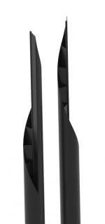
I think the principle will work. The bottom 4 pieces are "fast" while the top 2 are on normal speed. The close up joint is on normal. You can see the internal junction with flash, but you can't feel it with the finger. From the outside it has a distinct parting line but I'm confident I can get it removed, probably even less noticable than on the bottom 4.
Unfortunately I'm leaving on a trip today and will be away for 2 weeks meaning I will have to take a break with the physical tests.
Hi ellemanSorry Claudio for hijacking the thread.
I think the principle will work. The bottom 4 pieces are "fast" while the top 2 are on normal speed. The close up joint is on normal. You can see the internal junction with flash, but you can't feel it with the finger. From the outside it has a distinct parting line but I'm confident I can get it removed, probably even less noticable than on the bottom 4.
Unfortunately I'm leaving on a trip today and will be away for 2 weeks meaning I will have to take a break with the physical tests. View attachment 781776 View attachment 781777
no problem indeed, your model has increased interest in my projects.
I await developments.
Also in the twentieth century
Hi.
I found it interesting that you know what the Juan Portela did in Santiago de Compostela, in Galicia, is the speaker they called "organ sound" and that has many similarities with the Mr. Gandolfi's MDD, but this in the late 60s.
The Organsound – https://medium.com/@tek_fest_86155/o-organ-sound-ou-a-aproximaci%C3%B3n-ao-son-perfecto-444956c91ab7 | Portela Seijo
Organ Sound: Los creadores del extrano altavoz hecho en Galicia que le flipa a Micah P. Hinson | Tentaciones | EL PAIS
Organsound by Espadaysantacruz
YouTube
Greetings.
Hi xannHi.
I found it interesting that you know what the Juan Portela did in Santiago de Compostela, in Galicia, is the speaker they called "organ sound" and that has many similarities with the Mr. Gandolfi's MDD, but this in the late 60s.
The Organsound – [url]https://medium.com/@tek_fest_86155/o-organ-sound-ou-a-aproximaci%C3%B3n-ao-son-perfecto-444956c91ab7 | Portela Seijo[/url]
Organ Sound: Los creadores del extrano altavoz hecho en Galicia que le flipa a Micah P. Hinson | Tentaciones | EL PAIS
Organsound by Espadaysantacruz
YouTube
Greetings.
your report is very interesting. The points in common with organsoud could be many. The vertical tubes are suitable for emitting delayed and coherent sound waves by diffraction. The base probably contains a two-way from which the tubes radiate, almost certainly with lengths in logarithmic series, as in the organs. It can be an inspiration for those who want to make high-powered speakers with drivers from 6" to 15".
Listening impressions are also suited to MDD technology. In the YouTube movie (with the limits of the quality of the recording) I perceive a familiar air in the sounds reproduced with the 54m42 speakers.
If it has been patented, it should be possible to recover the drawings of the internal structure. I'm curious to see the contents of the base. Unfortunately (fortunately?) I only see it today. It is strange that during my patent practice I was never notified. The practice has lasted years and is now abandoned. I probably would have saved time and money, but I wouldn't have gone into the mechanisms of MDD technology. Now I could not build excellent loudspeakers with a few tens of euros (66c9, 54m42).
Last edited:
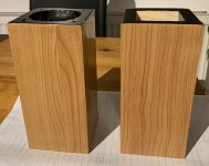
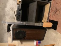
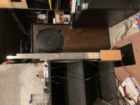
Here are the tube holders after vinyl self adhesive wallpaper application. Also, the painted bases. I will glue some foam to the bottom not to damage flooring. The L piece will be screwed to the small 19 mm riser to have more clearance for the magnet. Now I need to glue the tubes together and polish them. Then all will be mounted together for listening.
Attachments
Here are the tube holders after vinyl self adhesive wallpaper application. Also, the painted bases. I will glue some foam to the bottom not to damage flooring. The L piece will be screwed to the small 19 mm riser to have more clearance for the magnet. Now I need to glue the tubes together and polish them. Then all will be mounted together for listening.
Hi Pelanj
you know how to work wood better than me. While waiting for the test with the complete system a suggestion for photos, the tubes seem much larger than the actual dimensions. Perhaps there would be a better perception of size with a common object nearby: a coin, a can, a CD ...
Last edited:
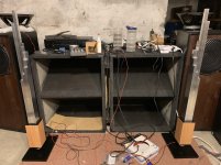
Finally, the speakers are now finished - almost. I just need to mount some permanent connectors, now there are just wires directly to the speaker terminals. The former nickname, Kaťuša, does not fit anymore, since I chose the spiral form, now they look more like a pair of skyscrapers - so I need to find another one. In the photos, I actually noticed I have swapped the left and right side. I will start a build thread with more details and pictures.
The funny thing is, my wife asked me where I wanted to place these and insisted on the living room But there I plan the higher 3D printed version, since it looks even better.
I wonder if this principle would work with compression drivers to have a higher efficiency two way speaker with 12" or 15" bass. I definitely need to try a Karlson and a K-tube, but that is a different project.
All in all, I highly recommend building an MDD speaker, the price/performance ratio is just great.
The funny thing is, my wife asked me where I wanted to place these and insisted on the living room
But there I plan the higher 3D printed version, since it looks even better.I wonder if this principle would work with compression drivers to have a higher efficiency two way speaker with 12" or 15" bass. I definitely need to try a Karlson and a K-tube, but that is a different project.
All in all, I highly recommend building an MDD speaker, the price/performance ratio is just great.
Attachments
Hi PelanjFinally, the speakers are now finished - almost. I just need to mount some permanent connectors, now there are just wires directly to the speaker terminals. The former nickname, Kaťuša, does not fit anymore, since I chose the spiral form, now they look more like a pair of skyscrapers - so I need to find another one. In the photos, I actually noticed I have swapped the left and right side. I will start a build thread with more details and pictures.
The funny thing is, my wife asked me where I wanted to place these and insisted on the living room
I wonder if this principle would work with compression drivers to have a higher efficiency two way speaker with 12" or 15" bass. I definitely need to try a Karlson and a K-tube, but that is a different project.
All in all, I highly recommend building an MDD speaker, the price/performance ratio is just great.
you won the race for the first complete replica of an MDD sound box. It makes a certain impact to see a copy made abroad by a person I've never met. Internet is convenient in these cases.
In the 3d version proposed by elleman the effect of the unique 700 mm section used in the 439h project with the material other than wood and the radial wave guides is to be verified. I can't do tests with this configuration, now I'm always testing waveguides side by side starting from 5-10 mm above the speaker cone in different materials and with different shapes.
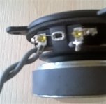
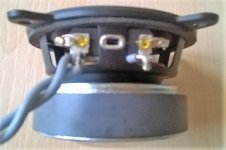
From the DIY (for the moment only pelanj can answer) I would like an opinion on my suggestion to pass one of the wires connecting the loudspeaker behind a radius of the basket. Do you perceive the difference or is it my self-conviction? In theory, you should never place ferromagnetic material inside a circuit with an audio signal.
In the Karlson and K-tube projects the effects of delayed diffraction are certainly important, for the moment I have never listened to them, I do not express opinions.
The 34c9 project has a very good price / performance ratio, but surprising results can be obtained even with materials other than aluminum such as: 66c9 paper, 54m42 alveolar polypropylene and more under test. In some cases the weight / performance ratio is exceptional.
Attachments
Last edited:
34c9 upgrade
Hello to all
an update on the construction of the 34c9 speakers.
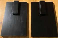
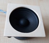
I added a 4 mm thick poplar plywood flange between the loudspeaker and the wooden support. This change eliminates the sealant and simplifies the mounting and dismounting of the speaker. All wooden parts were colored in black.
There are no variations in the quality of reproduction.
It should be noted that I used 3FE25 new speakers, in the first few minutes of listening the sound was very closed with too much bass and reduced highs.
link. 34c9
Hello to all
an update on the construction of the 34c9 speakers.
I added a 4 mm thick poplar plywood flange between the loudspeaker and the wooden support. This change eliminates the sealant and simplifies the mounting and dismounting of the speaker. All wooden parts were colored in black.
There are no variations in the quality of reproduction.
It should be noted that I used 3FE25 new speakers, in the first few minutes of listening the sound was very closed with too much bass and reduced highs.
link. 34c9
Attachments
- Status
- This old topic is closed. If you want to reopen this topic, contact a moderator using the "Report Post" button.
- Home
- Loudspeakers
- Full Range
- 34c9 a MDD full range speakers.