Can you get more into this 2 way with the tweeter and cardboard it's hard to tell how it's made from the pics can you please post pics of it so I can get a idea how it's done thanks in advance
In the 34c9 project the diffraction is used for two objectives: to generate delayed and coherent secondary waves, to make the diffuser omnidirectional. Normally in the design of the speakers there is a tendency to minimize the diffraction, I have not found on the internet suggestions to maximize it.
My previous thread is an invitation to experiment with the phenomenon of acoustic diffraction. On the Lavoce website I saw a high frequency compression unit on the home page, it reminded me of a possible 2-way drawing. Up to 1 Khz almost all electrodynamic loudspeakers are omnidirectional, if you want to detect the effect on the directive emission it is better to carry out tests with a tweeter.
By placing a sound wave guide (a pipe) in front of any speaker, sound waves are generated by diffraction on the opposite side. It is not a Hi-end system but it allows to verify the omnidirectionality of the issue. On the contact page there are links to pdf files and Pinterest pages, you can take inspiration from dozens of photos and drawings with waveguides of my projects. It is always full-range but the same guides also work with tweeters.
To make tests, any rigid or semi-rigid tube positioned in front of a loudspeaker is fine. To increase the acoustic diffraction holes or slit can be added. If a tweeter is not available, tests can be performed with a two-way facing upwards.
Attachments
I did some cutting and glueing yesterday - and I have severely broken the rule "measure twice, cut once". Therefore no pictures yet, there is some serious filling and sanding needed and even then, it will not be perfect. Most probably, I am going to put self adhesive wallpaper as finish so that it looks at least acceptable.
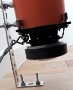
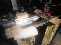
Just to illustrate, these are the tube holders before sanding - I just used leftovers I had, but I cut them too narrow - so the edges will not be perfect 90 degrees. I will select the best surface as the front and try to cover up with the self adhesive wallpaper.
I also did not install any mounting for the holding screws yet (by mistake) - I plan to use M5 threaded inserts, I hope they will hold the load.
In the lower inner corners, I will glue in some small triangles, so that the whole bottom forms a baffle so I will not have to use any putty, just weather seal strips. These triangles will also serve as holders/spacers for the tube assembly.
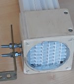
Claudio, I just wonder what is the reason to have a hole in the base for the magnet - is it to bring the assembly as low as possible? Would it work the same way with the speaker magnet above the base without any hole? Also, is the 5 mm distance between the tubes and the speaker critical? Would 8 mm be any significant difference? Also, what is the thickness of the steel bracket you use?
I also did not install any mounting for the holding screws yet (by mistake) - I plan to use M5 threaded inserts, I hope they will hold the load.
In the lower inner corners, I will glue in some small triangles, so that the whole bottom forms a baffle so I will not have to use any putty, just weather seal strips. These triangles will also serve as holders/spacers for the tube assembly.
Claudio, I just wonder what is the reason to have a hole in the base for the magnet - is it to bring the assembly as low as possible? Would it work the same way with the speaker magnet above the base without any hole? Also, is the 5 mm distance between the tubes and the speaker critical? Would 8 mm be any significant difference? Also, what is the thickness of the steel bracket you use?
Attachments
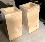
Just to illustrate, these are the tube holders before sanding - I just used leftovers I had, but I cut them too narrow - so the edges will not be perfect 90 degrees. I will select the best surface as the front and try to cover up with the self adhesive wallpaper.
I also did not install any mounting for the holding screws yet (by mistake) - I plan to use M5 threaded inserts, I hope they will hold the load.
In the lower inner corners, I will glue in some small triangles, so that the whole bottom forms a baffle so I will not have to use any putty, just weather seal strips. These triangles will also serve as holders/spacers for the tube assembly.
Claudio, I just wonder what is the reason to have a hole in the base for the magnet - is it to bring the assembly as low as possible? Would it work the same way with the speaker magnet above the base without any hole? Also, is the 5 mm distance between the tubes and the speaker critical? Would 8 mm be any significant difference? Also, what is the thickness of the steel bracket you use?
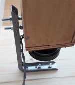
I saw that you made the support at least twice as long as my prototype, better you have more possibilities to fix the bracket.
The triangle instead of the sealant is fine. A further possibility is to build a flange as in the 54m42 project.
I don't think the distance between tubes and speaker is critical. The steel bracket section is 2.5 x 20 mm. The oscillation frequency also depends on the distance of the base.
I thought the hole for the magnet to avoid any interference with the base. These are minimal differences. The aesthetic improvement is evident.
Attachments
I am quite interested in the idea of your project. Can you advise me on an idea for new products? I am doing business on full range speakers and karaoke speakers. This is my website 96+ mẫu loa hội trường cho san khấu ngoai trời gia rẻ 08/2019
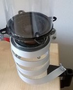
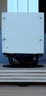
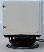
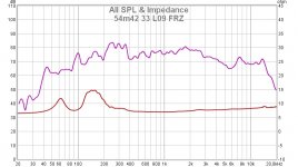
One unit is ready for measurements") The bracket is a bit soft, but still looks fine with the frequency of movement. The tubes will be glued by contact cement and polished, the bases will be covered by self adhesive wallpaper. I think I will not make a hole in the base, the smaller Nd magnet does not look too bad.
The bracket is a bit soft, but still looks fine with the frequency of movement. The tubes will be glued by contact cement and polished, the bases will be covered by self adhesive wallpaper. I think I will not make a hole in the base, the smaller Nd magnet does not look too bad.
I hope to plot some curves tomorrow.
The bracket is a bit soft, but still looks fine with the frequency of movement. The tubes will be glued by contact cement and polished, the bases will be covered by self adhesive wallpaper. I think I will not make a hole in the base, the smaller Nd magnet does not look too bad.I hope to plot some curves tomorrow.
Attachments
I'm glad the project is almost ready. I usually use the prototypes a couple of days trying to guess the result of the measures in advance. I measure later as confirmation.One unit is ready for measurements
I hope to plot some curves tomorrow.
I am very interested in your opinion on the effect of delayed sound fronts. There are no measurements about it, I am waiting to hear your impressions after the break-in (of the drivers and the ears).
claudio
The first measurements will be just to confirm I did everything right and to see the overall in room balance and low cutoff. I put together also the other one really quick, I am excited to listen to them tomorrow. I will try my two best SS and tube amps.
It aleady makes me think how to apply this principle to load a compression driver, it also reminds me the K-tube I always wanted to try.
It aleady makes me think how to apply this principle to load a compression driver, it also reminds me the K-tube I always wanted to try.
This sounds like a fascinating project. I'm interested in trying the 439h, which seems to have a good response down to 41hz, which appeals to me from my favourite driver 3fe22. I have a few lying around.
This version uses a lot of piping, which becomes quite expensive in steel, here in the UK. PVC box profile pipe is much better value.
Is there any reason you've used metal over plastic?
This version uses a lot of piping, which becomes quite expensive in steel, here in the UK. PVC box profile pipe is much better value.
Is there any reason you've used metal over plastic?
This sounds like a fascinating project. I'm interested in trying the 439h, which seems to have a good response down to 41hz, which appeals to me from my favourite driver 3fe22. I have a few lying around.
This version uses a lot of piping, which becomes quite expensive in steel, here in the UK. PVC box profile pipe is much better value.
Is there any reason you've used metal over plastic?
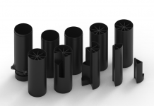
All the projects I presented use wave guides (tubes). All rigid and smooth pipes inside are suitable. From time to time I have chosen giving priority to parts of previous projects and to the cheapest and / or most comfortable materials to use. Wood, aluminum, rigid PVC and alveolar polypropylene are fine. I do not recommend paper or flexible PVC because deformations make the construction very complicated.
In the 439h project I had the wooden guide ready of the 669g project and I replaced the paper guides (too much distortion by increasing the volume) with aluminum, first with a linear and then logarithmic series. Extending the guides extends the response at low frequencies. In the 439h project there is the drawback that an important part of the high frequency energy is sent above the listener's head.
A compromise between bass response and treble diffusion is the 54m42 project (Thread 54m42 an MDD project (42 wave guides on a driver)). The guides range from 700 to 1400 mm and the resonance of the impedance is at about 65 Hz. The alveolar polypropylene has the advantage of being very economical compared to metal. To have the resonance of the impedance at about 40 Hz it must reach 2000 mm. I didn't do prototypes with lengths between 1000 and 2000 mm and I can't tell you if the treble feels good, nor confirm the 40 Hz. With alveolar polypropylene you can risk spending 30 euros for 2 meter strips, in the worst case they can easily be recovered and reduced in length.
Attachments
Yes, I see now on your website you have used PVC pipes. I think I will try the 227h to see if I like the sound. Thanks Claudio.
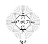
With seven guides I suggest using this logarithmic series for the lengths: 552, 610, 673, 743, 820, 906, 1000 mm or proportional values.
See post https://www.diyaudio.com/forums/full-range/341739-34c9-mdd-range-speakers.html#post5892954
Hi EllemanHello Claudio,
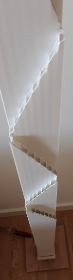
I did a 3d printable version of your 439h.
Did i understand correctly that the independent tubes start 700mm from the speaker?
congratulations for the work and for the rapidity of the realization. Have you also foreseen the possibility of suspension with a bracket or is the magnet resting on the floor?
I have done many projects and with the acronyms not managed in an optimal way I have favored the confusion. I will try to make order on the site, in the meantime summary for the DIY.
The latest MDD designs have the shortest waveguide length of half the longest length. The series is logarithmic and changes if it is a prototype with 7, 9 or N guides. Another variable is the shape of the circular, square, arched waveguides, the shape influences only the mechanical construction mode.
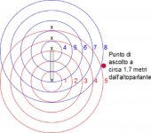
By increasing the length of the guides the FR extends downwards, the increase in length has a drawback, the energy of the high frequencies emitted by diffraction is concentrated in the upper part. In the prototypes I found the following approximate values of the first peak in the impedance module:
439h - max length 1.8 m, frequency 40 Hz
34c9 - max length 1.0 m, frequency 80 Hz
54m42 - max length 1.4 m, frequency 65 Hz
66c9 - max length 1.0 m, frequency 80 Hz
With 9 wave guides I used the logarithmic series 540, 583, 630, 680, 735, 794, 857, 926, 1000 mm compact series. If you want to extend the FR downwards, you can multiply everything by 1.4 or by 2, checking that you do not lose the high frequencies emitted above the listener's head. With the module system you've set up it should be simple.
Medium series 1.4 m: 773, 853, 942, 1040, 1148, 1268, 1400 mm
Large series 2 m: 1104, 1219, 1346, 1486, 1641, 1811, 2000 mm
Let me know how it sounds.
Did i understand correctly that the independent tubes start 700mm from the speaker?
The independent tubes start at 5-10 mm from the speaker in projects 34c9, 66c9 and 54m42.
They start at 700 mm in the 439h project.
With the measures indicated, the 439h project, with respect to other projects, has a greater extension on the low and less present highs.
Last edited:
Hello Claudio,
I did a 3d printable version of your 439h.
Did i understand correctly that the independent tubes start 700mm from the speaker?
elleman, this is such an elegant solution! Is that a realistic mock up or a photograph of the printed waveguide? I would love to try this out myself, but my CAD skills are next to nothing.
I can see this idea catching on quickly. Hopefully we get some more interesting takes on build methods.
Hi Elleman
congratulations for the work and for the rapidity of the realization. Have you also foreseen the possibility of suspension with a bracket or is the magnet resting on the floor?
I was thinking maybe to hang it in a cord from the roof?
elleman, this is such an elegant solution! Is that a realistic mock up or a photograph of the printed waveguide? I would love to try this out myself, but my CAD skills are next to nothing.
I can see this idea catching on quickly. Hopefully we get some more interesting takes on build methods.
It is just a quick render. My CAD skills are not great but it took me about 2 hours before going to bed last night.
If you have any ideas, just put them on a piece of paper and i will happily transform it in to usable drawings.
If you have any ideas, just put them on a piece of paper and i will happily transform it in to usable drawings.
I can only imagine getting it printed, built and measured will lead to the best feedback/improvements.
- Status
- This old topic is closed. If you want to reopen this topic, contact a moderator using the "Report Post" button.
- Home
- Loudspeakers
- Full Range
- 34c9 a MDD full range speakers.