Great project Claudio, Wow.
How would this work with TC9FDs?
In the projects I do not take into account the TS parameters. The prototypes made so far are not optimized for a specific driver and should also work with yours. I don't know the TC9FDs driver, the specifications have a little low efficiency.
The length of the high frequency guides is less than 1 meter and can be obtained by re-proportioning the series of the 21M7 project.
For low frequencies, the logarithmic series for the eight guides in spiral sheath of the 22C71L8 project can be used, re-proportioning it. Increasing the length of all the guides increases the response to low frequencies according to the rule L / 4 for TL.
Hello all,
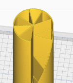
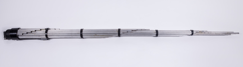
I have attached all the 3d printable files needed to print the spiral version seen here.
34c9 a MDD full range speakers.
It would consume about 1,3kg of filament to print one 100% solid. It is made for printers able to handle max height of 198mm.
I just got a 0,8mm nozzle for my printer so instead of continueing with the spiral version i will make another one that will be printable in Vasemode to recuse printing time and filament use.
Edit:Added STEP file for those who prefer that
Hi Elleman
thanks for the material you made available.
I want to remember that those who want to create MDD prototypes optimized for the reproduction of the medium-high range (for example satellites for 2.1 systems) can reduce the maximum length of the guides to 50 - 60 cm, saving time and material.
Hello All,
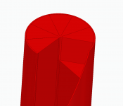
I made a new version of the spiral printable in Vasemode!
Let me know if you prefer another height of the pieces to accommodate your printers.
The base seems to be too big in STL format to upload, but you can find it as a STEP in the assembly.
It should print faster and because of vase mode get a nicer surface finish than the other one, although it does not have the assembly slots that make them latch on to each other so they would need to be glued to eachother... atleast untill i figure out a better solution!
Attachments
Last edited:
Well it was very much like in post 90.Hi Squeak
I didn't understand the geometry you suggested well (a drawing would be needed). If you propose a single waveguide with small holes distributed on the walls I have already tried the solution in some prototypes with which I started the patent practice, then abandoned (acoustic diffractor and 665g prototype).
The single guide with multiple holes generates coherent and delayed sound wave fronts by diffraction (as in MDD projects) but does not simplify the problems of resonances. Many resonances distributed at different frequencies partially compensate each other. With a single guide you would always have only one resonance that should be perfectly matched with the driver and listening room.
Only the outer turns would probably need to get tighter or else most of the sound energy is going to escape through the path of least resistance.
You’d probably need very little, if any support between the wall of the spiral. Definitely not full length walls since they would just invite the resonant modes you tried to get rid of. If not in the air columns, then in the structure itself.
The whole idea reminds me of and is probably in family with the long Karlson clam.
Well it was very much like in post 90.
Only the outer turns would probably need to get tighter or else most of the sound energy is going to escape through the path of least resistance.
You’d probably need very little, if any support between the wall of the spiral. Definitely not full length walls since they would just invite the resonant modes you tried to get rid of. If not in the air columns, then in the structure itself.
The whole idea reminds me of and is probably in family with the long Karlson clam.
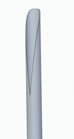
So basically you mean like only keeping the outer tube but with the "spiral" slit opening?
Edit: just remembered i got tweeters like that https://www.diyaudio.com/forums/ful...onator-0-53x-dual-tc9fds-317.html#post5658102
Attachments
Last edited:
Well it was very much like in post 90.
Only the outer turns would probably need to get tighter or else most of the sound energy is going to escape through the path of least resistance.
You’d probably need very little, if any support between the wall of the spiral. Definitely not full length walls since they would just invite the resonant modes you tried to get rid of. If not in the air columns, then in the structure itself.
The whole idea reminds me of and is probably in family with the long Karlson clam.
In the old 665g project the configuration is similar to Karlson's configuration. I used a series of holes (I also tried with straight line cuts) to generate the phenomenon of acoustic diffraction. I switched to multiple guides for more reasons.
I wanted to increase the phenomenon of diffraction, the prototype sent a substantial fraction of sound energy of the higher frequencies upwards. With more waveguides, the sound energy sent by diffraction towards the listening point increases.
No need for complex calculations to simulate uniform emission over the entire length of the profile. Assuming the losses proportional to the length of the guide and using a logarithmic series with Lmax = 2 Lmin, there is a double power emission in the shorter wave guide than the longest one. It is only 3 dB. It is possible to precisely modify the fraction of energy to be emitted at a point in space by checking the length of each waveguide.
The diffraction emission of a guide does not interact with the sound fronts that run alongside the guides, eliminating the turbulence that can be generated within the Karlson configuration or in a horn system.
Resonances (like acoustic diffraction) are not a problem in MDD technology but resources. Any rigid waveguide has specific resonances and also the Karlson configuration or old projects 669g, 667g. Using a single guide for the reproduction of low frequencies, it is necessary to tune it with the driver used and position the speaker in a suitable point in the listening environment. There are more likely to be a good listening with the multiple resonance guides distributed over an entire octave, they partially compensate each other, with the driver and with the listening environment. For each frequency there is a path suitable for transferring sound energy from the speaker membrane to the listening point. See neutral cabinet.
Last edited:
So basically you mean like only keeping the outer tube but with the "spiral" slit opening?
Edit: just remembered i got tweeters like that https://www.diyaudio.com/forums/ful...onator-0-53x-dual-tc9fds-317.html#post5658102
No your own render is pretty much it: 34c9 a MDD full range speakers.
Not so much a slit as a narrowing of the spiral, towards the outer edge, to avoid all the sound energy taking the path of least resistance.
The whole thing relies on the problem of small source that gives great dispersion vs a large source with lots of bass.
It solves it by distribution.
Think of it as a folded Karlson slot.
Google the Karlson Rocket speaker.
Last edited:
I’m quite certain you are on to something. I’m just not sure you have boiled the idea down to it’s robust essence.In the old 665g project the configuration is similar to Karlson's configuration. I used a series of holes (I also tried with straight line cuts) to generate the phenomenon of acoustic diffraction. I switched to multiple guides for more reasons.
I wanted to increase the phenomenon of diffraction, the prototype sent a substantial fraction of sound energy of the higher frequencies upwards. With more waveguides, the sound energy sent by diffraction towards the listening point increases.
No need for complex calculations to simulate uniform emission over the entire length of the profile. Assuming the losses proportional to the length of the guide and using a logarithmic series with Lmax = 2 Lmin, there is a double power emission in the shorter wave guide than the longest one. It is only 3 dB. It is possible to precisely modify the fraction of energy to be emitted at a point in space by checking the length of each waveguide.
The diffraction emission of a guide does not interact with the sound fronts that run alongside the guides, eliminating the turbulence that can be generated within the Karlson configuration or in a horn system.
Resonances (like acoustic diffraction) are not a problem in MDD technology but resources. Any rigid waveguide has specific resonances and also the Karlson configuration or old projects 669g, 667g. Using a single guide for the reproduction of low frequencies, it is necessary to tune it with the driver used and position the speaker in a suitable point in the listening environment. There are more likely to be a good listening with the multiple resonance guides distributed over an entire octave, they partially compensate each other, with the driver and with the listening environment. For each frequency there is a path suitable for transferring sound energy from the speaker membrane to the listening point. See neutral cabinet.
That said, your speakers are very appealing. Both in appearance and in ideas.
I’m quite certain you are on to something. I’m just not sure you have boiled the idea down to it’s robust essence.
That said, your speakers are very appealing. Both in appearance and in ideas.
I agree. I'd be interested in trying to make the concept/physics work in a box format. I am no designer, but I'm messing about on sketchup with a grid labyrinth within an obelisk shaped rectangular box. Something layered so it can be broken down into 2d CAM format for CNC.
One question would be whether right angles will affect the path responses in a bad way?
I’m quite certain you are on to something. I’m just not sure you have boiled the idea down to it’s robust essence.
That said, your speakers are very appealing. Both in appearance and in ideas.
Thanks Squeak. MDD technology is still under development.
I agree. I'd be interested in trying to make the concept/physics work in a box format. I am no designer, but I'm messing about on sketchup with a grid labyrinth within an obelisk shaped rectangular box. Something layered so it can be broken down into 2d CAM format for CNC.
One question would be whether right angles will affect the path responses in a bad way?
Another thought I had is whether an isobaric driver arrangement would help with overall SPL/distortion levels? This might allow the path lengths to remain the same, as opposed to a bigger driver??
I am preparing a structure that allows to fix the spiral sheaths of the 22C71L8 project in predefined positions and to change the driver (up to 5 ”) leaving everything else unchanged.
You can reduce the space occupied by using straight waveguides with right angle fittings. The total surface of the sections of the waveguides must be similar to the surface of the driver used. I have not done any tests for now, my suggestion is to use the structure of an optical periscope, with surfaces inclined at 45 degrees at each angle of 90 degrees.
To have a 3D effect, the suggestion is to distribute the outputs of the waveguides in height and depth. The distance between the right and left channel is already sufficient for the lateral dimension.
The isobaric driver has a purpose if you want to carry out the 22C71L8 project with the spiral sheaths replaced by a sealed box. I don't see any advantages if you stick with the rear emission with waveguides. I have not yet made high SPL measurements, I live in an apartment building.
I am preparing a structure that allows to fix the spiral sheaths of the 22C71L8 project in predefined positions and to change the driver (up to 5 ”) leaving everything else unchanged.
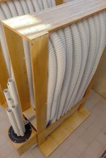
In the "MDD Multi Delays Diffraction (Multi TL, omnidirectional, single drive, ...)" tread I inserted a post on the MMDXH135 prototype. It has an omnidirectional MDDFL front loading for high frequencies, very simple to make, and an MDDBL rear loading for low frequencies that requires more work. I will continue to insert the new posts in the "MDD Multi Delays Diffraction (Multi TL, omnidirectional, single drive, ...)" tread.
The MDDHX135 prototype goes beyond the limits of projects that use the 3FE25 driver of only 3 ". The MDDBL rear loader can be adapted to accommodate even 6 ” or larger diameter drivers. The speaker remains accessible and can be easily replaced by removing the MDDFL front loading.
On the MDDHX135 page I published photos and indications for making a replica. It takes more time for measurements.
Attachments
The MDD 34c9 project (replicated by pelanj) with the aluminum waveguides is the best aesthetically successful one.
In the thread MDD Multi Delays Diffraction (Multi TL, omnidirectional, single drive, ...) other projects with better acoustics are presented. Greater bass extension and greater MDD effect. The aesthetics are for a laboratory, not for a home. MDD tecnology web site.
Before the summer I will publish other configurations that you can choose from, I already have a prototype on test.
Last edited:
Hi Claudio
here's a 1940 patent I bumped into when searching for stuff related to the Bose "K-tube" patent.
https://patentimages.storage.googleapis.com/24/a6/f6/243bee1170b78f/US2225312.pdf
here's a 1940 patent I bumped into when searching for stuff related to the Bose "K-tube" patent.
https://patentimages.storage.googleapis.com/24/a6/f6/243bee1170b78f/US2225312.pdf
Hi Freddi
The device reported is very similar to that of the Gutbucket's post https://www.diyaudio.com/forums/pla...nidirectional-single-drive-6.html#post6155092.
In both cases they are directional microphones. By replacing the microphone with an FR driver they could function as omnidirectional loudspeakers due to the phenomenon of acoustic diffraction.
I don't know if the linear size distribution of the waveguides would give a smooth frequency response.
As I wrote earlier it would probably be beneficial to have some spacer walls at regular intervals in the spiral to give structural rigidity, and to keep unnecessary resonant modes in check.
And also as in Warrens patent, differentiating between the low impedance outer part of the spiral and the inner, higher impedance part.
This could be done in a number of ways, the most straightforward one being just to make the spiral gradually more narrow towards the outside.
Warren P. Mason was a bona fide genius. If he “dabbled” in this, there is definitely something to it.
Last edited:
- Status
- This old topic is closed. If you want to reopen this topic, contact a moderator using the "Report Post" button.
- Home
- Loudspeakers
- Full Range
- 34c9 a MDD full range speakers.