Hi,
Note:- The term directivity is used to mean constant narrow directivity, not omni which also is constant directivity.
CBT arrays have very nice directivity control in the vertical plane, but poor horizontal control of beamwidth, its an omni horizontally. A dipole CBT turns into a dipole horizontally (ie 60 degrees) while still retaining its excellent vertical control as per the physical arc. Even in the vertical plane, below the pattern loss frequency, where a normal CBT turns omni, the dipole CBT turns into a dipole.
Now, the rear of a dipole is often a problem to deal with in usual point source speaker but not so in a dipole CBT. The arc places the sound source somewhere rear of the speaker on the ground so it would suffice to absorb/diffuse only that small area, isnt it?
So, why no DIY groundplane dipole CBTs?
Regards,
WA
Are you sure that backside response will be symmetrical with dipole nulling sideways? The curve is opposite, I don't believe that it could work and give any benefit. A straight line array could work and has been done as dipole too.
This is guessing, someone should make a sim or make a proto and measure it!
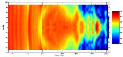
By the way here is test with measurements and Keele's notes of CBT24. Horizontal directivity looks quite uneven, even with eq.
Epique CBT24 Line Array Loudspeaker Review | Audioholics
This is guessing, someone should make a sim or make a proto and measure it!
By the way here is test with measurements and Keele's notes of CBT24. Horizontal directivity looks quite uneven, even with eq.
Epique CBT24 Line Array Loudspeaker Review | Audioholics
The backside will be symmetric at least in the dipole operation region. The backside is not important from regularity/irregularity perspective as long as its absorbed or diffused like usual dipoles.Are you sure that backside response will be symmetrical with dipole nulling sideways? The curve is opposite, I don't believe that it could work and give any benefit.
The benefit is that we achieve a stronger front radiation vs the back and the sides.
Measurements in figure 6b and 7 seem quite good. http://faculty.tru.ca/rtaylor/publications/cbt_dipole.pdfBy the way here is test with measurements and Keele's notes of CBT24. Horizontal directivity looks quite uneven, even with eq.
Do note that driver's own radiation pattern dominates at higher frequencies and that is irrespective of whether its a normal CBT or a dipole.
That paper lookes familiar, I might have seen seen it before. I don't quite grasp what would be dipole cutoff freq for a typical CBT, perhaps somewhere between 500-1000Hz, below that there will be dipole roll-off 6dB/oct. Baffle width has also an influence on this.
Looks like beneficial for eq demand, but lowers efficiency - a subwoofer is needed. Directivity between 1-2khz will remain wide, which is problematic regarding reflections in a room.
The size and shape of a CBT is perhaps the biggest problem that prevents it getting popular.
Looks like beneficial for eq demand, but lowers efficiency - a subwoofer is needed. Directivity between 1-2khz will remain wide, which is problematic regarding reflections in a room.
The size and shape of a CBT is perhaps the biggest problem that prevents it getting popular.
When Keele discusses low frequency patterns he isn't discussing the topic in the context of small rooms. DIYers designing for home spaces can ignore that because we have to use multiple subs to control low frequency modal behavior.
Regardless of one's chosen speaker, a home DIYer must always use multi-subs below their room transition region.
If you want to design a speaker for large rooms or outdoor spaces (e.g. your backyard) then low frequency radiation patterns are important.
Regardless of one's chosen speaker, a home DIYer must always use multi-subs below their room transition region.
If you want to design a speaker for large rooms or outdoor spaces (e.g. your backyard) then low frequency radiation patterns are important.
Attachments
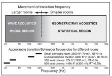
In small rooms you only need to worry about how a CBT handles radiation above the transition frequency.
In regard to the OP question, CBTs don't focus a pattern to the rear like a lens focusing light rays. If you took a physically curved CBT and bent it forward it would work the same way as one curved backward. The only thing the curve does is create a difference in time between one speaker and another in the array.
In regard to the OP question, CBTs don't focus a pattern to the rear like a lens focusing light rays. If you took a physically curved CBT and bent it forward it would work the same way as one curved backward. The only thing the curve does is create a difference in time between one speaker and another in the array.
Subs, atleast stereo, if not more, are a given.A CBT 24 needs subwoofer(s) anyway. dipole radiation pattern would realize in range 100-1000Hz most likely. Whether it is beneficial vs. "normal omni" is another question...
The lowering of rear radiation (by absorbtion/diffusion) is a big plus I feel when placed near listener's front wall. The rear illuminated area is quite small so treatment is needed only in that area.
In regard to the OP question, CBTs don't focus a pattern to the rear like a lens focusing light rays. If you took a physically curved CBT and bent it forward it would work the same way as one curved backward.
If we see 3D radiation patterns in Don's paper http://faculty.tru.ca/rtaylor/publications/cbt_dipole.pdf, figure 6 we notice that the plots are symmetrical. The speaker is not in the center of the plot but a bit forward. So, if we go backwards from the speaker, we will see collapsing area of the arc and then a virtual point source somewhere behind (its the center of the beamwidth arc, not physical arc). If we go further back, we will see the same expanding radiation as we see in the front. We could call it 'perfect symmetry with offset'. The idea is to absorb just before that virtual point source, its a small area so practically doable.
That might just be the angle of view they chose in that paper. Look at "9. APPENDIX 2. FULL SET OF POLAR BALLOONS FOR THE CBT ARRAYS" in this paper where he shows top down views in addition to oblique. https://www.xlrtechs.com/dbkeele.com/PDF2/Keele (2003-03 AES Preprint) - CBT Paper3.pdf
I totally understand why people think the physical curve makes the source come from a point on the ground. Visual intuition makes us think that's what's happening. However, you can build straight CBTs using time delays instead of a physical curve. The physical curve allows Keele to build the CBT without individually amped drivers and multiple DSP channels per speaker.
Today, we can buy really inexpensive high quality amps ($2.50 each) and fairly inexpensive DSP. Dayton sells an 8 channel DSP for $150.
Thanks to Jim Griffin, I recently found out you can build a straight CBT-24 with only three channels of DSP. Project: CBT array, balanced DML, delay curved
That means the 8 channel Dayton DSP could run two straight CBTs and have two channels vacant for a center channel (or subs).
Once you have the straight CBT you can choose to enclose it or run it dipole. As you already know, the enclosure would not need to be built for low frequency in small rooms. Instead, you'd build an enclosure for mids and run your CBT above the transition frequency.
DSP + amps = straight CBT. Straight CBT + small room transition frequency = easy enclosure.
I totally understand why people think the physical curve makes the source come from a point on the ground. Visual intuition makes us think that's what's happening. However, you can build straight CBTs using time delays instead of a physical curve. The physical curve allows Keele to build the CBT without individually amped drivers and multiple DSP channels per speaker.
Today, we can buy really inexpensive high quality amps ($2.50 each) and fairly inexpensive DSP. Dayton sells an 8 channel DSP for $150.
Thanks to Jim Griffin, I recently found out you can build a straight CBT-24 with only three channels of DSP. Project: CBT array, balanced DML, delay curved
Keele actually used only three shading banks for his CBT24 project. The lowest 12 drivers (Bank 1) have a 0 dB weight, the next 6 higher drivers (Bank 2) have a -3.5 dB attenuation, and the top 6 drivers (Bank 3) are weighted to a -8.0 dB attenuation level. The bottom two banks achieve the weighting levels via series/parallel driver connections while the weighting for the top drivers are aided by a resistive power divider.
That means the 8 channel Dayton DSP could run two straight CBTs and have two channels vacant for a center channel (or subs).
Once you have the straight CBT you can choose to enclose it or run it dipole. As you already know, the enclosure would not need to be built for low frequency in small rooms. Instead, you'd build an enclosure for mids and run your CBT above the transition frequency.
DSP + amps = straight CBT. Straight CBT + small room transition frequency = easy enclosure.
Last edited:
That might just be the angle of view they chose in that paper. Look at "9. APPENDIX 2. FULL SET OF POLAR BALLOONS FOR THE CBT ARRAYS" in this paper where he shows top down views in addition to oblique. https://www.xlrtechs.com/dbkeele.com/PDF2/Keele (2003-03 AES Preprint) - CBT Paper3.pdf
I totally understand why people think the physical curve makes the source come from a point on the ground. Visual intuition makes us think that's what's happening. However, you can build straight CBTs using time delays instead of a physical curve.
The curved CBT, straight delay curved CBT and dipole CBT all behave differently front and back.
The above link is for curved CBT.
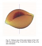
A curved CBT has an acoustic focal point, see vertical line of Fig 21 in above paper. If, we ignore that, then the forward and rear are symmetrical.
Same for dipole CBT as well, only difference is that in the horizontal plane the CBT is a dipole at a much higher frequency and in the vertical plane its a dipole at lower frequency.
A delay curved CBT has no such focal point since its reproducing a section of a spherical wavefront from both the sides
I do have plans to build one soon.
Last edited:
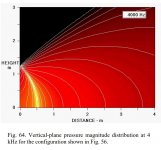
I don't know if this is the Figure 21 you're referring to. I also included Figure 64 from Keele's 5th paper discussing ground plane CBTs. It's the closest thing I could find to a near proximity radiation pattern of the curved array.
After you build a curved dipole version and take photos of the rear treatment I'll be able to see what you're talking about.
After you build a curved dipole version and take photos of the rear treatment I'll be able to see what you're talking about.
Attachments
In another paper the Thompson Rivers University researchers and Don Keele have a paper about the implementation of a ground plane dipole CBT. This work includes photos, implementation details, and reponses for a 10 driver array made with 2.5" drivers. One link to this work is:
https://pdfs.semanticscholar.org/fb0e/ed92716c1963cc3bc734515b9137d664623e.pdf
https://pdfs.semanticscholar.org/fb0e/ed92716c1963cc3bc734515b9137d664623e.pdf
Last edited:
^Yea that paper shows the importance of baffle width and driver diameter well. Multiple drivers help to get decent spl down low despite dipole roll-off.
One important aspect of dipoles is the backside radiation adding late reflections in the room. That should be studied too. Just damping those will kill some of the magic.
One important aspect of dipoles is the backside radiation adding late reflections in the room. That should be studied too. Just damping those will kill some of the magic.
Yes, Juhazi you have it on that dipole CBT implementation. A wider baffle, closer driver spacing, more drivers, equalization, etc. all would help improve the results of a ground plane dipole CBT.
Don Keele provided a pre-release link to this paper at the MWAF back in July 2017. It convinced me to build my Modified CBT24 version using a curved CBT enclosure cabinet vs. a dipole array. The rest is history for me at least.
Jim
Don Keele provided a pre-release link to this paper at the MWAF back in July 2017. It convinced me to build my Modified CBT24 version using a curved CBT enclosure cabinet vs. a dipole array. The rest is history for me at least.
Jim
Dipole radiation and "directivity" depends mostly on baffle dimensions, typically we look at horizontal dispersion. The wider the baffle the lower dipole radiation dies.
In that recent dipole-cbt the narrow baffle helped to get dipole pattern up to 2kHz horizontally, and thereafter driver diameter starts to make radiation narrow.
More about this here Dipolplus - Alles über offene Schallwände
and more specifically Dipolplus - Alles über offene Schallwände
In that recent dipole-cbt the narrow baffle helped to get dipole pattern up to 2kHz horizontally, and thereafter driver diameter starts to make radiation narrow.
More about this here Dipolplus - Alles über offene Schallwände
and more specifically Dipolplus - Alles über offene Schallwände
Yes, the issue with dipoles is that most users want to improve the lower frequency response which generally means a wider baffle to combat dipolar roll off. But as Juhazi points out a wider baffle does you no favors for higher frequency usage.
Bottom line is that a CBT array (arrayed in the vertical plane) is a design that places its resources on vertical response control. The horizontal response of the array is dictated by individual driver response.
Thus CBTs offer a wide horizontal response and a controlled vertical response that allows excellent sound while standing or sitting.
Thus CBTs offer a wide horizontal response and a controlled vertical response that allows excellent sound while standing or sitting.
Vertical response turned out to be a bigger deal than I expected. It's a very nice feature.
- Status
- This old topic is closed. If you want to reopen this topic, contact a moderator using the "Report Post" button.
- Home
- Loudspeakers
- Full Range
- Why no DIY groundplane dipole CBTs?