Hi,
I'm sharing work in progress of a Constant Beamwidth Transducer/Technology ground plane array (CBT) using Distributed Mode Loudspeaker exciter/actuator panels (DML).
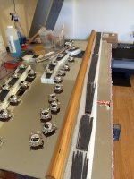
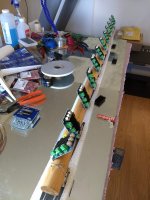
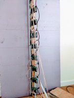
66 inch/167 cm straight CBT array using time delay to approximate physical curve shading at -6 dB half-angle: Cosine 47°, Legendre 36°, Chebyshev 25°. Shading (virtual arc) can be reconfigured with the DSP by adjusting the time delay for each bank.
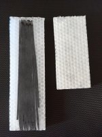
Twelve total actuators per array are positioned 5.5 inches/14 cm center-to-center. The actuators are attached to a wooden spline (hand railing from Home Depot) and excite a poly honeycomb core covered with fabric. One side of the core was left as unmodified fabric. The other side was covered with resin and loose - unwoven - carbon fiber strands then sanded to a flat finish. Each panel is 3 inches/7.62 cm wide and 0.5 inches/1.27 cm thick. They currently use separate panels for each Bank, however, I don't think that's necessary. I think you could do this with one narrow and tall panel with even spacing between the actuators.
(Edit: this paragraph is wrong. Read this post for accurate information Project: CBT array, balanced DML, delay curved) Like Don Keele's CBT-24, this array uses five shaded banks rather than constant shading. Each bank is separately controlled by a DSP channel and each actuator is powered by an amplifier tuned to the same voltage.
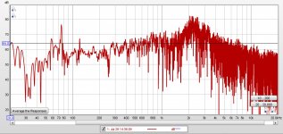
I have not taken good frequency measurements with REW. I have taken bad (sloppy) measurements with REW. At present, the array has an unequalized audible resonance between around 1000Hz to 4000Hz with a peak at 2200Hz. It hurts my ears and my dog's ears. I'll equalize it out at a later time. I have only measured the array while Legendre shaded at 36 degrees. I have not measured it while shaded in Cosine or Chebyshev configuration yet.
I've attached photos of work in progress. I will also upload the spreadsheets I used to calculate shading in a second post.
I'm sharing work in progress of a Constant Beamwidth Transducer/Technology ground plane array (CBT) using Distributed Mode Loudspeaker exciter/actuator panels (DML).
66 inch/167 cm straight CBT array using time delay to approximate physical curve shading at -6 dB half-angle: Cosine 47°, Legendre 36°, Chebyshev 25°. Shading (virtual arc) can be reconfigured with the DSP by adjusting the time delay for each bank.
Twelve total actuators per array are positioned 5.5 inches/14 cm center-to-center. The actuators are attached to a wooden spline (hand railing from Home Depot) and excite a poly honeycomb core covered with fabric. One side of the core was left as unmodified fabric. The other side was covered with resin and loose - unwoven - carbon fiber strands then sanded to a flat finish. Each panel is 3 inches/7.62 cm wide and 0.5 inches/1.27 cm thick. They currently use separate panels for each Bank, however, I don't think that's necessary. I think you could do this with one narrow and tall panel with even spacing between the actuators.
(Edit: this paragraph is wrong. Read this post for accurate information Project: CBT array, balanced DML, delay curved) Like Don Keele's CBT-24, this array uses five shaded banks rather than constant shading. Each bank is separately controlled by a DSP channel and each actuator is powered by an amplifier tuned to the same voltage.
I have not taken good frequency measurements with REW. I have taken bad (sloppy) measurements with REW. At present, the array has an unequalized audible resonance between around 1000Hz to 4000Hz with a peak at 2200Hz. It hurts my ears and my dog's ears. I'll equalize it out at a later time. I have only measured the array while Legendre shaded at 36 degrees. I have not measured it while shaded in Cosine or Chebyshev configuration yet.
I've attached photos of work in progress. I will also upload the spreadsheets I used to calculate shading in a second post.
Attachments
Last edited:
Here is the spreadsheet I used to calculate shading. I'm not sure I did the calcs right so don't rely on them. But it is what I'm using right now.
I have attached two versions (Excel, Open Office) of the same spreadsheet.
I have attached two versions (Excel, Open Office) of the same spreadsheet.
Attachments
Last edited:
Also, I have no science for the way I modified the poly honeycomb core panel. Covering both sides with resin made an extremely stiff panel. I wanted some damping so I left one side unmodified. The carbon fiber? I don't know why. I don't have any idea it even helps. It was just an attempt to retard reflected resonances from the panel edges.
Ah, the goal. Wide sound stage + precise imaging + high intelligibility for home theater.
According to posts I've read by Earl Geddes, wide sound stage and precise imaging are apparently in acoustical conflict with one another. I'm going to try to overcome it with three CBTs: one center channel in a full-arc configuration and two ground plane half-arc stereo channel CBTs at ±60° off center axis, time delayed by 80 milliseconds (based on something I read by Floyd Toole regarding convincing sound stage.)
The center channel CBT will be shaded for narrow horizontal dispersion and operate in stereo. I'm still trying to figure out the panel geometry, probably wide and short. The panel will probably be wide enough to reach ±30° off center listening axis at each end ends. But, still trying to figure this part out.
I think my room crosses the Schroeder transition frequency around 120 or 150Hz. I'll design the CBTs to work above the transition and use Earl Geddes' research and experience to address low frequency modal room behavior: one subwoofer for the very low frequencies, multi-subs for the upper bass frequencies. In my room, I think the low-low frequency transition region is around 62Hz. So, one sub for 20Hz to 62Hz and multisubs for 62Hz to 120/150Hz.
Floyd Toole said you get the best intelligibility for home theater by turning down the side channels relative to the center channel. So the whole system will rely heavily on digital signal processing adjustment between the 3.1 channels as well as CBT array shading based on the type of entertainment. Live recordings will be wide with 80 millisecond delays. Studio recordings will be narrow with no delays. Movies will emphasize the center channel, and possibly switch to mono in the center. I'll figure it out when I get there.
Last edited:
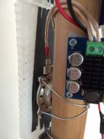
Neat project! Impressively low frequency reach. Each driver has its own amp? Are those TPA3116’s? How many channels of DSP do you have? More details on the electronics and signal processing when you get the chance.
I'll wind up cutting off the low frequency with equalization and handing it off to multi-subs designed to calm the modal region. The lows due to array length are an accidental side effect. On the other hand, Earl Geddes said you can let mains run as low as they naturally go and equalize them in conjunction with the multi-subs.
Yes, each driver has its own amp and is adjusted to deliver the same volts. Yes, TPA3116s. Five DSP channels on each array, one for each Bank. I have a total of 48 DSP channels devoted to the final system: all arrays plus subs.
I'll do the DSP tuning at the end so I won't have that information for a while. Electronics should be very easy. Just power supply, TPA3116 amps, and the DSP. The TPA3116s will probably even be able to run the multi-subs. So I won't have any expensive amplifiers in the entire system. The vast majority of the money is in the DSP.
Last edited:
Nice project. You ve chosen dsp delay to keep the arc angle variable, which is a good thing.
Do note that to hit a particular pattern loss frequency, the narrower the coverage angle the greater the height of the array. For narrow angles, you may need very large array, that may cause a problem with the 30 degree target for the center channel
Do note that to hit a particular pattern loss frequency, the narrower the coverage angle the greater the height of the array. For narrow angles, you may need very large array, that may cause a problem with the 30 degree target for the center channel
Last edited:
Bradley,
Your new CBT project presents an interesting implementation of how to attain equivalent performance between an actively delayed straight line array versus the time delays inherent of a curved array. Your use of DML drivers is also novel.
In your first message in this thread you stated:
"Like Don Keele's CBT-24, this array uses five shaded banks rather than constant shading. Each bank is separately controlled by a DSP channel and each actuator is powered by an amplifier tuned to the same voltage."
Keele actually used only three shading banks for his CBT24 project. The lowest 12 drivers (Bank 1) have a 0 dB weight, the next 6 higher drivers (Bank 2) have a -3.5 dB attenuation, and the top 6 drivers (Bank 3) are weighted to a -8.0 dB attenuation level. The bottom two banks achieve the weighting levels via series/parallel driver connections while the weighting for the top drivers are aided by a resistive power divider.
I also used the same weighting levels as Keele for my Modified CBT24 project as you can read at this thread:
My New Line Array--It's a Modified CBT24
Good luck with your project.
Jim
Last edited:
Nice project. You ve chosen dsp delay to keep the arc angle variable, which is a good thing.
Do note that to hit a particular pattern loss frequency, the narrower the coverage angle the greater the height of the array. For narrow angles, you may need very large array, that may cause a problem with the 30 degree target for the center channel
Thanks for the information. Could you explain more about narrow dispersion angles relative to array length, please. I'm not familiar with the topic.
I also used the same weighting levels as Keele for my Modified CBT24 project as you can read at this thread:
My New Line Array--It's a Modified CBT24
Thanks for the correction. Shading is something I don't understand in detail. I'll read your thread and adjust the CBT spreadsheets.
Bradley,
Keele's and my shading scheme for the CBT24 are for a Legendre function. I'm not suggesting that you change your number of shading levels as you have different number of drivers. Perhaps you can better approximate the rolloff function with additional attenuation banks.
You mentioned in your first post that you were considering other attenuation schemes. Keele's approach is to plot the attenuation function level in dB versus a linear scale of the number of drivers across the aperture. The y-axis is the attenuation amount in dB. The x-axis is scaled by the number from drivers 1 to 24 for the Legendre function which varies from 0 to 1. Thus the Legendre function slopes from 0 dB to about -12 dB down for the highest driver. For the CBT24 example the stepped approximation varies from the Legendre plot by 0 dB for the first 4 or 5 drivers but trends toward a + 2 dB error for the 12th driver. The -3.5 dB step level errs from the true function by -1.5 dB for driver 13 and goes to a +2 db error for driver 18. For drivers 19 to 24 the error varies from -2.5 dB for driver 19 to a +4 dB approximation for driver 24. Keep in mind that the lowest 12 drivers provide more sound radiation while the two strings of 6 drivers each add less volume to the mix.
Viewing the attenuation function plotted across the aperture can help you determine the number of drivers to assign to each attenuation step. Through this process we are not seeking perfection as a good approximation is adequate.
Jim
Last edited:
Keele's approach is to plot the attenuation function level in dB versus a linear scale of the number of drivers across the aperture. The y-axis is the attenuation amount in dB. The x-axis is scaled by the number from drivers 1 to 24 for the Legendre function which varies from 0 to 1. Thus the Legendre function slopes from 0 dB to about -12 dB down for the highest driver.
Thank you for the explanation. I'll need to figure that out for the Cosine and Chebychev functions.
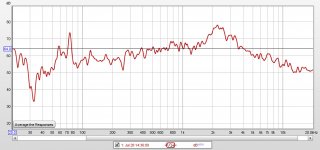
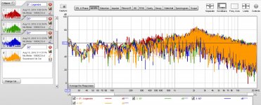
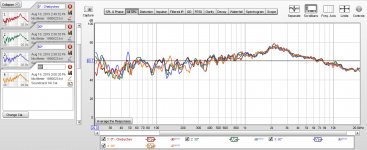
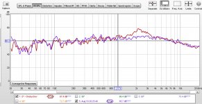
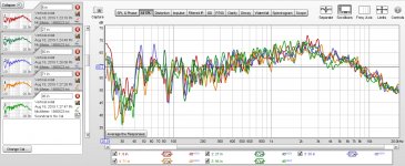
Got my protractor out and measured the array axis frequency response. Mic placed 2 meters away at one meter high for the axis measurements.
First is Legendre shading, 36°. Raw and 1/24 smoothed.
First is Legendre shading, 36°. Raw and 1/24 smoothed.
Attachments
Last edited:
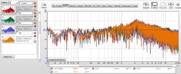
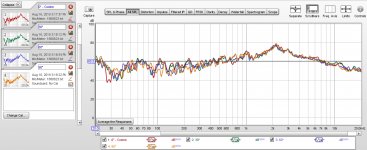
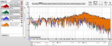
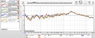
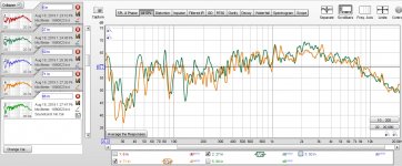
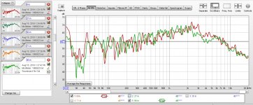
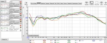
Vertical frequency response measurements. Mic six feet away from speaker: 6, 27, 50, 71, and 95 inches high. In a room with a 96 inch ceiling. I separated out measurements for 6 inches vs 96 inches and 27 inches vs 71 inches. Finally, a 1/3rd smoothed graph.
Chebychev shading.
I also included an impulse response for the vertical measurements.
Chebychev shading.
I also included an impulse response for the vertical measurements.
Attachments

- Home
- Loudspeakers
- Full Range
- Project: CBT array, balanced DML, delay curved