My Infinite Line Source project
Brief history - I have built a line array (LA) with the same drivers in the past - Halair Column - my line array build (20 FR drivers)
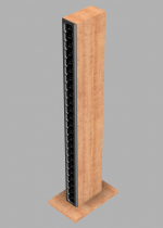
My main goals this time is to improve sound quality, by increasing numbers of drivers from 20 to 24 and making a "extreme" cabinet")
The outside will be conventional with a rectangular box but the driver volume will be elliptical and the "unused" volume will be filled with "epoxy granite - EG" which is simply epoxy and sand in this case.
EG is often used for machine bases (CNC) as they are easy to cast, are dimensionally stable and also act as a mass damping device. Both attributes come in handy for my intended application.
Speaker weight is estimated to about 80+kg/side.
With 24 drivers per speaker I will group them into two lines of 12 speakers each => I need 2 amps per side. My current LA is connected to a 5x125W amp
but utilize only two of them => I have 3 channels that are unused.
With a 20% cone area increase and 2x available power I expect improved system capacity + a much improved cabinet should help even further on sound quality
Fullrange LA require EQ which I dont have solids plan for yet, but it wont be my old analogue EQ I currently use.
Updates:
Brief history - I have built a line array (LA) with the same drivers in the past - Halair Column - my line array build (20 FR drivers)
My main goals this time is to improve sound quality, by increasing numbers of drivers from 20 to 24 and making a "extreme" cabinet
The outside will be conventional with a rectangular box but the driver volume will be elliptical and the "unused" volume will be filled with "epoxy granite - EG" which is simply epoxy and sand in this case.
EG is often used for machine bases (CNC) as they are easy to cast, are dimensionally stable and also act as a mass damping device. Both attributes come in handy for my intended application.
Speaker weight is estimated to about 80+kg/side.
With 24 drivers per speaker I will group them into two lines of 12 speakers each => I need 2 amps per side. My current LA is connected to a 5x125W amp
but utilize only two of them => I have 3 channels that are unused.
With a 20% cone area increase and 2x available power I expect improved system capacity + a much improved cabinet should help even further on sound quality
Fullrange LA require EQ which I dont have solids plan for yet, but it wont be my old analogue EQ I currently use.
Updates:
- Link - Front baffle design finalized
- Link - CNC'ing the front baffles
- Link - Cabinets constructed and standing, awaiting to be filled with sand mixed with epoxy
- Link - Casting process has begun, 50kg per cabinet will be used
- Link - First line is playing
- Link - December 9th, second cabinet is playing.
- Both speakers are operational, currently tweaking the EQ/DSP to optimize it
Attachments
Last edited:
Try casting the internal volume of the individual chambers to be a 5 sided tall pyramid. A Dagger shape as used on many of my speakers. About 1.2L is all that’s needed. They don’t support any regular resonance modes and sound transparent like an OB. Stuff them progressively with fiberglass etc dense st the rear vertex and looser towards driver cone. Leave about 1in empty space behind driver. Line walls adjacent to driver with felt or melamine foam for first 2in.
Good to see you back in action! I like the look of that front baffle! I'll get the popcorn out for this ride. Take hour time, do it once and do it right!
We´ll see wont we
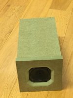
I have machined two test baffles, primarely for testing fit & tolerances but also to see how it may be finished. Test baffle is regular 19mm MDF.
Very quick and dirty spray paint applied to raw MDF, with a proper primer/sealing and black satin...it could be quite sexy...
@XRK971 - thanks for the idea
Not sure I fancy creating 48x 5-sided pyramids though! I do have a concept I consider regarding internal diffusing + stuffing.Attachments
Last edited:
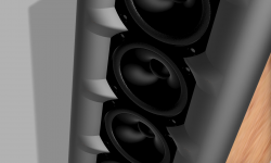
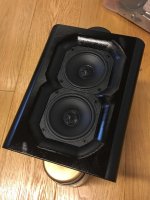
Poor little dust caps.
Yeah, finally got to replace the broken ones with fresh stock
Some practical progress was made yesterday:
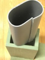
1 - Material for the tube tested, to see how "playable" it is regarding reshaping. Also to verify the final width when compressed from round Ø100mm to 84mm height (elliptical shape)
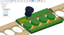
2 - preparing the cut files (CNC) for the front baffle.
Since my CNC is limited to 380mm travel along the Y-axis I need to tile the carve. The CNC is open front and back so I can feed longer material.
So the intention is a single one-piece front baffle, and the cut files are split into 3 different sections, top 4 drivers, mid 4-drivers and bottom 4 drivers.
Total carve time per baffle is approx 3hrs, I can spend less time carving but 3hrs should give me good surface finish, requiring very little pre-paint work
My original intent regarding the tubes was to glue them in place with EG, but it occured to me last night that I can slit them longside and simply use them for casting, pulling them out after the EG have cured. This will allow for more EG but more importantly - a single EG matrix per array vs 4 cells of EG per speaker. The EG wont conform easily when cast thickness approach <2mm.
1 - Material for the tube tested, to see how "playable" it is regarding reshaping. Also to verify the final width when compressed from round Ø100mm to 84mm height (elliptical shape)
2 - preparing the cut files (CNC) for the front baffle.
Since my CNC is limited to 380mm travel along the Y-axis I need to tile the carve. The CNC is open front and back so I can feed longer material.
So the intention is a single one-piece front baffle, and the cut files are split into 3 different sections, top 4 drivers, mid 4-drivers and bottom 4 drivers.
Total carve time per baffle is approx 3hrs, I can spend less time carving but 3hrs should give me good surface finish, requiring very little pre-paint work
My original intent regarding the tubes was to glue them in place with EG, but it occured to me last night that I can slit them longside and simply use them for casting, pulling them out after the EG have cured. This will allow for more EG but more importantly - a single EG matrix per array vs 4 cells of EG per speaker. The EG wont conform easily when cast thickness approach <2mm.
Attachments
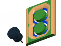
I'm wondering why you don't opt for a back mounted driver... as now the baffle is protruding beside the frame, not really forming an extension/wave guide shape.
It doesn't even have to be back mounted if the baffle is split up (like I did).
Have you tested the off axis performance of this shape?
It doesn't even have to be back mounted if the baffle is split up (like I did).
Have you tested the off axis performance of this shape?
I havent really given that much thought so far, the thickness of the material is what pretty much dictated the overall "waveguide shape", no acoustic considerations have been done yet.
For my first LA I didnt do any testing prior, just built it and use them, but I will test this one, both in terms of impedance and off-axis response.
The only way I can rear-mount them would be with a similar arrangement to yours, a clamshell setup.
For my first LA I didnt do any testing prior, just built it and use them, but I will test this one, both in terms of impedance and off-axis response.
The only way I can rear-mount them would be with a similar arrangement to yours, a clamshell setup.
It is the option of that CNC of yours that could make it interesting to experiment some .
I know my back mount isn't optimized but do wonder what it would do. A simple test with a single driver could shed some light here. I just copied a shape/size from a published test by a German forum user that showed real promise.
I liked the radius on the outer edge, but wonder if a shallow wave guide shape would help off axis performance.
.I know my back mount isn't optimized but do wonder what it would do. A simple test with a single driver could shed some light here. I just copied a shape/size from a published test by a German forum user that showed real promise.
I liked the radius on the outer edge, but wonder if a shallow wave guide shape would help off axis performance.
A simple test with a single driver could shed some light here. I just copied a shape/size from a published test by a German forum user that showed real promise.
I liked the radius on the outer edge, but wonder if a shallow wave guide shape would help off axis performance.
I can easily design a two-part front baffle for the test rig, a thin baffle the Vifa is rear-mounted and a outer curved wave guide that snap on top. By doing so I can change wave guide designs without altering the speaker/box... Not sure I should curse you or praise you for giving me more "thinkload"
@XRK971 - thanks for the idea Not sure I fancy creating 48x 5-sided pyramids though! I do have a concept I consider regarding internal diffusing + stuffing.
Oh, I was under the impression that the rear cabinet was going to be molded/cast from synthetic granite - so thought you could stick a 5-sided form in them while being cast for a quick rear chamber. But if not, I agree it’s too much work.
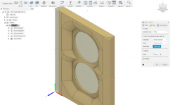
Not a lot of playtime today but made a forming jig for the chamber molds and a mock-up of the diffusor plate.
The diffusor will be CNC´d out of 6mm plasterboard and lined with foam/felt.
Main purpose is to break up the rear wall reflection by diffusing/dispersing the timing of the waves.
Also traced the actual and final shape of the chamber form so I could do the length calculations.
So while not much to show for, I think I have got on to a good headstart - considering this is intended to be a winter project
I now have enough to finish my test chamber
Attachments
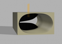
That's a Karlson aperture inside the enclosure? Interesting.
Yes it is, main intention is to break up the rear wall reflections by diffusion

It is
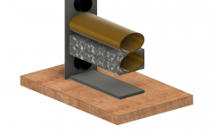
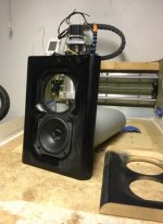
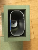
Construction of test chamber complete, casting epoxy / sand during the weekend Then impedance sweeps can be made to finalize stuffing ratio in front of/rear of diffusor plate.
The longside slit in the plastic tube is to help prying it out after the EG matrix have cured. So the test cabinet will also be used to verify method of construction..! Rather fail to pull this one out vs the 24 next ones!!
Construction of test chamber complete, casting epoxy / sand during the weekend
Then impedance sweeps can be made to finalize stuffing ratio in front of/rear of diffusor plate.The longside slit in the plastic tube is to help prying it out after the EG matrix have cured. So the test cabinet will also be used to verify method of construction..! Rather fail to pull this one out vs the 24 next ones!!
Attachments
- Status
- This old topic is closed. If you want to reopen this topic, contact a moderator using the "Report Post" button.
- Home
- Loudspeakers
- Full Range
- HalAir Aeralis - Fullrange Line Array (Vifa TC9-18-08)