
Todays effort 
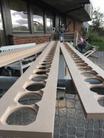
First CNC-stage completed included cabinet rear walls.
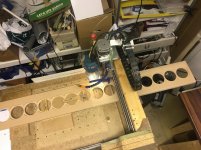
I had a CNC-crash again today but managed to abort it in time, no damage done to the router or baffle - phew!
I experienced some binding on the CNC Z-axis (up/down) causing it to loose position. I need to trust this axis when I will contour the baffle surface so time to go it some TLC. MDF chips/dust probably packing up in the bearings...
Anyways, first stage is complete with 2 baffles done and 3 precut rear walls.
The rear walls are 137mm wide, the baffles are 168mm and sidewalls 15mm. This give me a 1mm room for glue etc.
First CNC-stage completed included cabinet rear walls.
I had a CNC-crash again today but managed to abort it in time, no damage done to the router or baffle - phew!
I experienced some binding on the CNC Z-axis (up/down) causing it to loose position. I need to trust this axis when I will contour the baffle surface so time to go it some TLC. MDF chips/dust probably packing up in the bearings...
Anyways, first stage is complete with 2 baffles done and 3 precut rear walls.
The rear walls are 137mm wide, the baffles are 168mm and sidewalls 15mm. This give me a 1mm room for glue etc.
Attachments
Never knew how the speakers are wired, can someone enlighten me?
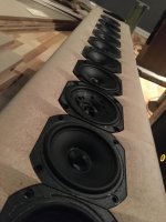
For my 20 driver array (mk1) I have 5 groups of 4 drivers in series, and each groups is parallell to eachother.
The impedance for each groups is 32ohm (nom.) but when 5 of these are parallell the impedance drop to 6,3ohm (32/5=6,3)
This makes sense then, but if they are all connected to a single point without any crossover, there is no post equalization? I am fascinated by your project!For my 20 driver array (mk1) I have 5 groups of 4 drivers in series, and each groups is parallell to eachother.
The impedance for each groups is 32ohm (nom.) but when 5 of these are parallell the impedance drop to 6,3ohm (32/5=6,3)
This makes sense then, but if they are all connected to a single point without any crossover, there is no post equalization? I am fascinated by your project!
The drivers all receive the same signal so any EQ is done prior to the amplifier stage.
Must be exciting each time you start a job
The CNC have "homing switches" which syncronize machine with design, so with that as a reference I can re-home to re-establish design sync
(within precision of the switches) As it happened today I was imideately able to power down the router, preventing damage to it which did happen last time three weeks ago. The machine itself is not strong enough to destroy itself LOL
When a stepper stalls there is a specific sound to it, so keepeing my "ears on it" with my hand close to the panic button....I also slowed don the rapid and accelenration rates for that axis giving me less chance to stall / more time to react.
Last edited:
@dewdrop - this is going to take a while
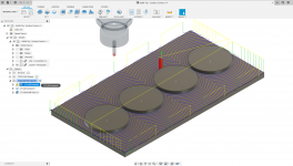
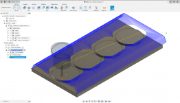
Some progress is made, the files for contour surfacing the baffle I need an arrangement that keep the precarved baffles aligned with design/3D surface.
In order to efficiently do that I opted to make a "driver opening negative" that I can mount the precut baffle over.
Some progress is made, the files for contour surfacing the baffle I need an arrangement that keep the precarved baffles aligned with design/3D surface.
In order to efficiently do that I opted to make a "driver opening negative" that I can mount the precut baffle over.
Attachments
Some progress
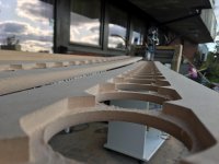
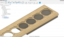
First baffle has started its "face surgery" procedyre, contouring of the waveguides. So far so good... The upper 8 driver openings are done and here its mounted in preparation of the 3rd.
As I can only do 4 drivers at the time I needed a fixture to make sure I kept it all in alginment, so a driver opening "negative" fixture plate was machined.
Two sections done, four to go for the first baffle, scheduled for later today.
Attachments
Last edited:
Phew..... first baffle fresh out of the CNC-machine
I am extremely happy that it came out this good, after having mechanical issues, router break-down I was feeling very anxious and baby-sat the machine during the final stages for baffle #1.
It came out goooood
I am extremely happy that it came out this good, after having mechanical issues, router break-down I was feeling very anxious and baby-sat the machine during the final stages for baffle #1.
It came out goooood
Attachments

For my 20 driver array (mk1) I have 5 groups of 4 drivers in series, and each groups is parallell to eachother.
The impedance for each groups is 32ohm (nom.) but when 5 of these are parallell the impedance drop to 6,3ohm (32/5=6,3)
Looks great! Im envious of your abilities (and patience)!
In one of your threads or maybe wesayso's thread somewhere there was a drawing (schematic) for series/parallel wiring.
Any clue as to where?
Ive been searching but cant find it anywhere. I'm looking to use 28 or 29 per side while keeping approx. 8 Ohm load.
Sorry for the high jack...
It has taken me quite some time to get to this stage, the desire for a mk2 build is a few years old already - but due to distractions and side-projects I ended up with a CNC which ultimately was the catalyst for mk2 project start
I doubt much progress is made this weekend as my 7yr old daughter is have her birthday parties (yes, plural) tomorrow
With the CNC rigged for surface shaping of the baffles I will do the second one before doing the side walls.
But when that is done I can:
Regarding wiring, I will wire each speaker and feed the wires out on the back side. The rear wall will be a sandwich of EG and 2xMDF and the middle MDF-plate will have channels for wiring. The rear (exteriour) MDF plate will be removable. That way I can rewire is need be, either for 2x12 driver setup or 1x24 should anything change in the future amp-wise
I doubt much progress is made this weekend as my 7yr old daughter is have her birthday parties (yes, plural) tomorrow
With the CNC rigged for surface shaping of the baffles I will do the second one before doing the side walls.
But when that is done I can:
- Order 20kg of casting epoxy
- Assemble the cabinet walls, no rear walls yet
- Glue in the oval shaped cast guides
- Create a shaker table strong enough to support the speaker array
- Cast it!
- Glue in the rear wall, (1x MDF) and flip it over
- Cast the rear wall with epoxy/sand (EG) aswell so all walls is EG-lined (Wiring per driver need to be completed prior to this stage)
Regarding wiring, I will wire each speaker and feed the wires out on the back side. The rear wall will be a sandwich of EG and 2xMDF and the middle MDF-plate will have channels for wiring. The rear (exteriour) MDF plate will be removable. That way I can rewire is need be, either for 2x12 driver setup or 1x24 should anything change in the future amp-wise
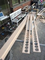
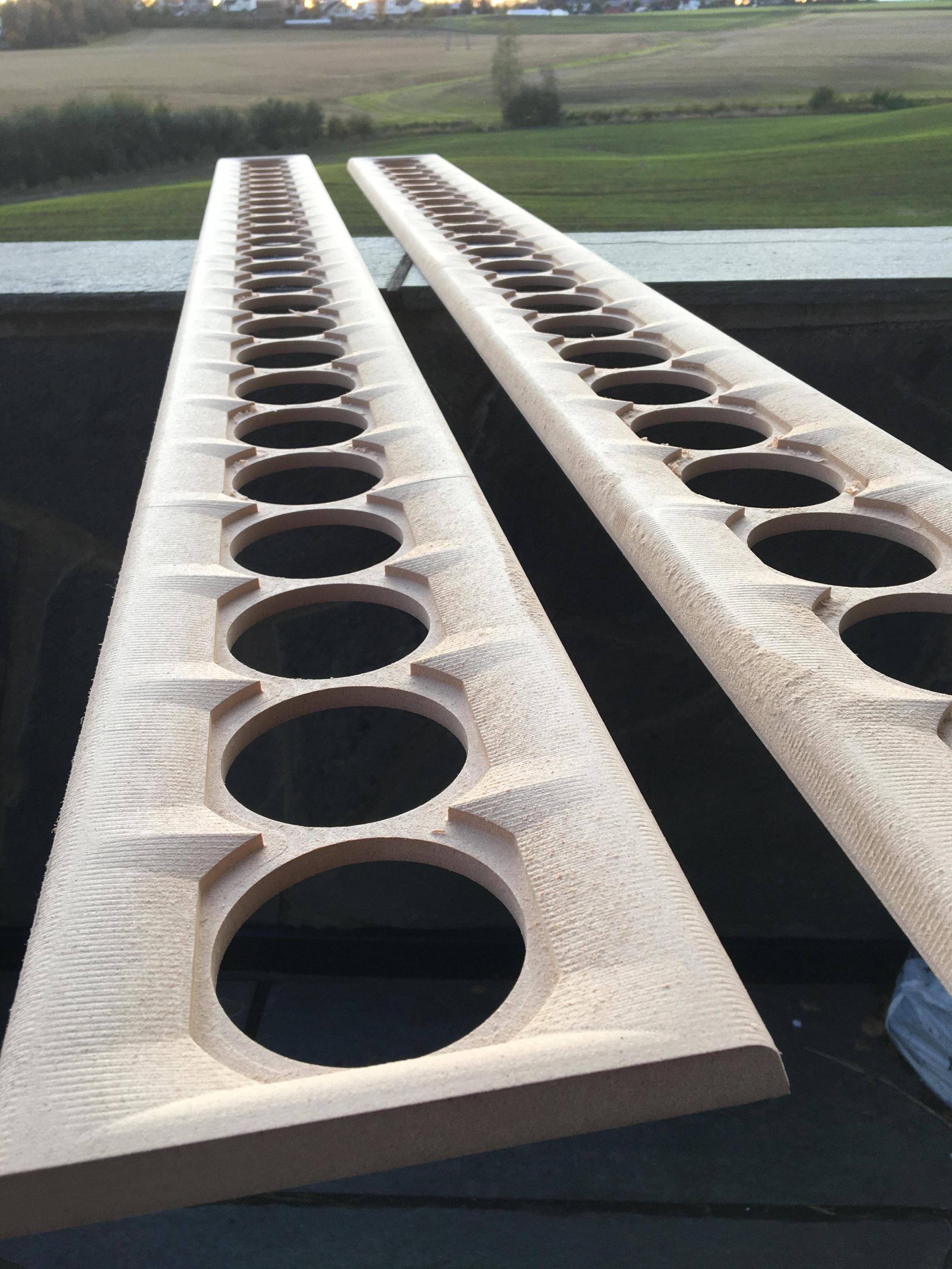
The baffles are done, no more CNC´for these
Here is a slow-mo video clip of the final baffle - YouTube
Photo of the pair, it looks much coarser on the photo in real life. I could have machined them to with much finer resolution but => a lot more machining time (and possibilities of failures..)
Here is a slow-mo video clip of the final baffle - YouTube
Photo of the pair, it looks much coarser on the photo in real life. I could have machined them to with much finer resolution but => a lot more machining time (and possibilities of failures..)
Attachments
Last edited:
Looks great! wondering how much machine time you have invested in them.
I would have liked to do something like that myself but its too much when paying an hourly rate on someone else's machine. So I settled for surface mount drivers and CNC drilled pilot holes for the mounting screws and a bevel in back cut with a V bit.
Early on, I did some AxiDriver sims that showed this kind of surface sculpting does make a difference in the top half octave but especially for rear mounted drivers.
And the other thing was worrying about having enough material left after sculpting to keep the baffle in one piece until final assembly where it would be braced.
Based purely on Fusion360 carve estimate the total machining time per baffle is 3hrs. 1hr for the cutouts/openings and another two hrs for the surface.
Time for preparation/setup/fixtures/cursing etc probablya bit more
When I buildt my first pair CNC wasnt an option, so I went with drilled holes/raised mounting/chamfering from the rearside too.
Time for preparation/setup/fixtures/cursing etc probablya bit more
When I buildt my first pair CNC wasnt an option, so I went with drilled holes/raised mounting/chamfering from the rearside too.
- Status
- This old topic is closed. If you want to reopen this topic, contact a moderator using the "Report Post" button.
- Home
- Loudspeakers
- Full Range
- HalAir Aeralis - Fullrange Line Array (Vifa TC9-18-08)