i have a 9" wide baffle. dual drivers. so one driver fullrange the other will be rolled off with an inductor.
I have tried a couple of different places for values of inductors. ranges from 1mH to 3mH.
What would be a good starting point? I tried the Edge software and also this one:
Loudspeaker Diffraction Loss and Baffle Step Compensation Circuits
i could get 2x inductors but would like to have an opinion. maybe split the difference and get a 2mH?
Typically i start at 0.707-1 times the BS(F3) which is on 1st approximation 4560/w where width=w is in inches (so 400-570Hz).
Note tha you will get 6 dB more bass level when the 2nd woofer kicks in. This is often to much, one has to balance the covering off of the response on axis due to baffle step and the increas ein power response (too much) in the power response. I rearly find compensation to work well.
With 2 woofers i’d wire in series & put a big cap across the driver you want to roll-off. This will not boost the bass, but will reduce LF excursion by a factor of 4.
dave
yes thanks for the reply. i was going to try both ways. plus i may tune the system really low. i will try 50,40, and maybe 30hz. its in the 34L enclosure with the 2x Alpair 10p's.
would it be possible to place a resistor in series with the driver that gets rolled off? or would that mess up other things? or use a higher dcr inductor.
would it be possible to place a resistor in series with the driver that gets rolled off? or would that mess up other things? or use a higher dcr inductor.
why the cap across the BSC filter?
I don't think I would need that for a 1.5 way system as I am trying to completely roll off the 2nd driver. I don't think I even need a resistor in parallel with the inductor.
In the case of 2 fullrange drivers, one with just an inductor in series with it... how do we determine the mH? All the formulas I have seen have resistors in parallel with inductor.
Thanks!
Dave, one of the things that has scared me off from trying a 2.5 way design is the horrible resonant peak (when modeling in hornresp) when using a passive crossover below about 700Hz or so. Have you found the series wired with cap approach ro be more or less tame in this regard?
The problem is that in the simulations there is not only a peak but it seems to move the resonance up in frequency and it steepens the final rolloff.
The problem is that in the simulations there is not only a peak but it seems to move the resonance up in frequency and it steepens the final rolloff.
why the cap across the BSC filter?
I don't think I would need that for a 1.5 way system as I am trying to completely roll off the 2nd driver. I don't think I even need a resistor in parallel with the inductor.
In the case of 2 fullrange drivers, one with just an inductor in series with it... how do we determine the mH? All the formulas I have seen have resistors in parallel with inductor.
Thanks!
Without giving it much thought or being set up to do any network designing, just posted the links to design BSC as part of a dividing network, assuming it would help you figure out what component
If you can find an acceptable trade-off between too much mids/HF overlap Vs the 'close enough' 1st order required for BS, then sure, just use an inductor.
GM
the horrible resonant peak (when modeling in hornresp)
??? Please elaborate and post the HR record
My 'knee jerk' response is you're seeing one of the many spikes [or dips] HR's math model predicts [to infinity and beyond
") ], which has no real world losses factored in to attenuate them to insignificance.
], which has no real world losses factored in to attenuate them to insignificance.GM
I’m not quite sure what you are describing? Where is the peak?
dave
Typically near and slightly above fs. In fairness some drivers seem to be less prone to it and the further from fs the crossover is the less pronounced. Tonight I will see if I can post up an example.
I first noticed the effect when investigating crossing below fs where the effect is pronounced so it may be less serious than I am remembering when significantly above fs.
Last edited:
Typically near and slightly above fs.
That should have nothing to do with the driver, but with the box design.
dave
As I looked back it seems the problem is pretty much just when ported or otherwise extending response by enclosure design. Sealed enclosures don't show as much change.
The first graph shows the Eminence Delta 15LFA in ported enclosure and the second is sealed.
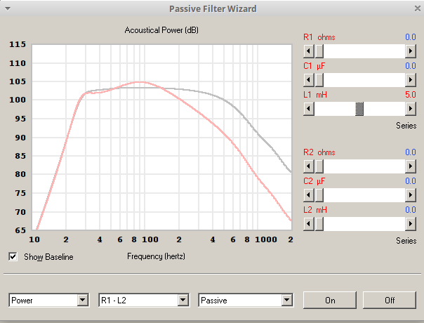
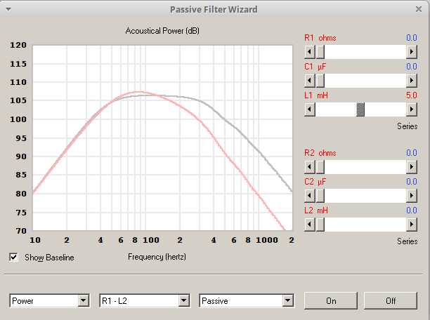
The first graph shows the Eminence Delta 15LFA in ported enclosure and the second is sealed.
Attachments
Right. If the XO is sufficiently close to the upper impedance peak for them (mostly the primary inductor) to interact & throw out the frequency / amplitude response compared to what is intended, then you can prevent this by flattening the upper peak with a series LCR conjugate / Zobel*. Downside is it usually needs a lot of microfarads, but at these frequencies, an electrolytic is usually acceptable if budget is tight & you can shunt it with a low value MKP, F&F or similar if desired. Basic MKTs or MKPs aren't spectacularly expensive though, so if the budget stretches & the larger size is acceptable, they are a better option if possible.
*Debatable whether the 'Zobel' moniker is strictly correct, but it's fairly commonly used & serves as a reasonable handle.
*Debatable whether the 'Zobel' moniker is strictly correct, but it's fairly commonly used & serves as a reasonable handle.
Last edited:
- Status
- This old topic is closed. If you want to reopen this topic, contact a moderator using the "Report Post" button.
- Home
- Loudspeakers
- Full Range
- baffle step compensation results