I've been studying/working on line arrays for quite a while. First to understand them, next to decide what to build and what driver to use in it, and finally to actually build a pair. This is too long a story to tell all at once so I'll skip to near the end.
My interest has always been to design speakers that integrate well into the room and avoid boundary interference. Corner horns do almost a perfect job of avoiding interference from the walls; mine didn't have enough vertical directivity and were two large for the living room in my new house. Line arrays twist that problem 90 degrees but walls are easier to pad than floor and ceiling. Some boundary interference is inescapable but by designing array that fits tightly against a wall or into a corner I've moved the boundary interference so high in frequency that only a nominal thickness of absorber will be needed. Or so I think...
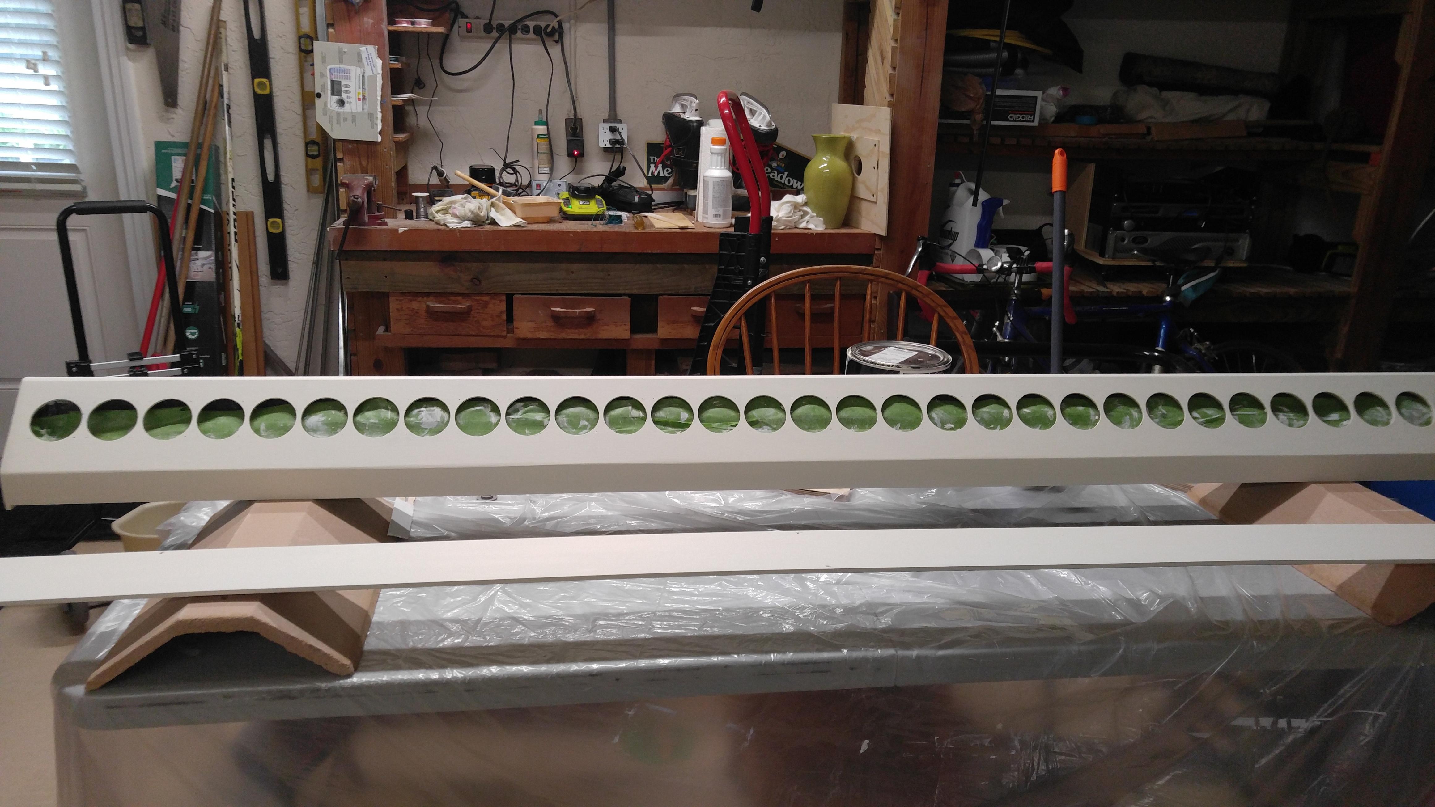
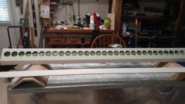
I chose SB65WBAC25-4 based on Jim Griffin's recommendations and my own measurements and listening tests. I'm using 32 per side wired 4 parallel groups of 8 in series for 8 ohms nominal Z.
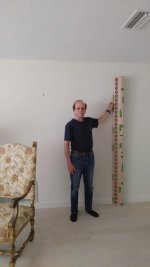
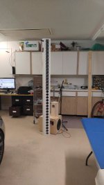
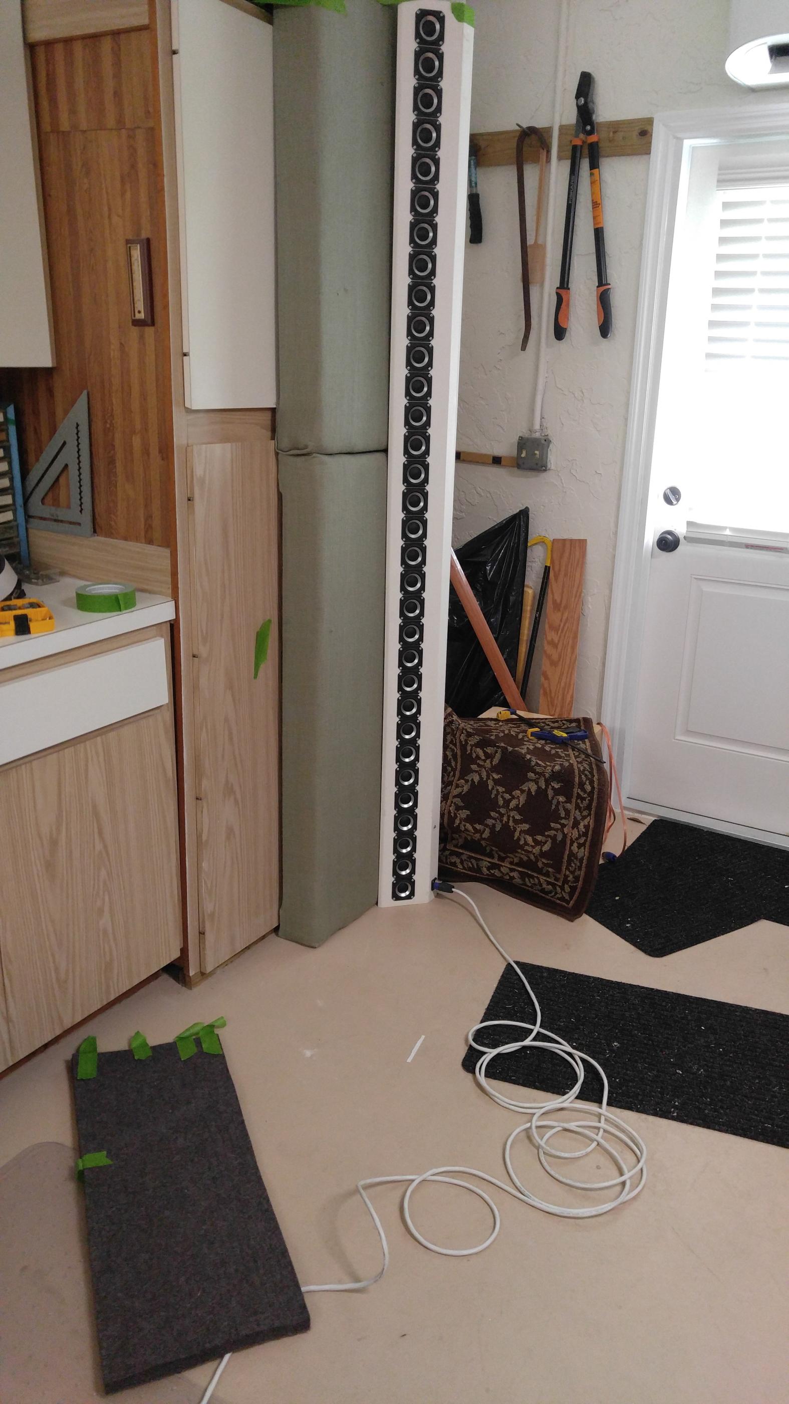
Here is me with a tape-up of the first array up in its intended position.

Except for the baseboard, the close end of the toed in baffle would be only 12 mm from the wall. At the other end baffle, its just 2" deep. Total enclosure volume is only 7.5L and predicted QTC=1. This small size is one of the benefits of using the SB65 rather than the TC9.
Yesterday, I got the 2nd coat of paint of the first cabinet and hope to spend a good part of today wiring them.
My interest has always been to design speakers that integrate well into the room and avoid boundary interference. Corner horns do almost a perfect job of avoiding interference from the walls; mine didn't have enough vertical directivity and were two large for the living room in my new house. Line arrays twist that problem 90 degrees but walls are easier to pad than floor and ceiling. Some boundary interference is inescapable but by designing array that fits tightly against a wall or into a corner I've moved the boundary interference so high in frequency that only a nominal thickness of absorber will be needed. Or so I think...
I chose SB65WBAC25-4 based on Jim Griffin's recommendations and my own measurements and listening tests. I'm using 32 per side wired 4 parallel groups of 8 in series for 8 ohms nominal Z.
Here is me with a tape-up of the first array up in its intended position.
Except for the baseboard, the close end of the toed in baffle would be only 12 mm from the wall. At the other end baffle, its just 2" deep. Total enclosure volume is only 7.5L and predicted QTC=1. This small size is one of the benefits of using the SB65 rather than the TC9.
Yesterday, I got the 2nd coat of paint of the first cabinet and hope to spend a good part of today wiring them.
Attachments
First listening test
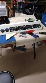
I jumped the gun and started listening to the first 8 drivers while I installed the next 8. That sounded so good I stood it up and stood back a ways where it was even better. Taking a break now while my sore fingers heal and i wait for UPS to deliver the hardware I need to finish it off.

I jumped the gun and started listening to the first 8 drivers while I installed the next 8. That sounded so good I stood it up and stood back a ways where it was even better. Taking a break now while my sore fingers heal and i wait for UPS to deliver the hardware I need to finish it off.
Attachments
I am very interested. I have a similar size constraint.
I may need to place speakers so they are very close to a wall and aimed somewhat alongside the wall, not aimed perpendicular to the wall. I had the same thought about very short path for reflections from the wall and will watch for your assessment.
Thanks,
Tom
I may need to place speakers so they are very close to a wall and aimed somewhat alongside the wall, not aimed perpendicular to the wall. I had the same thought about very short path for reflections from the wall and will watch for your assessment.
Thanks,
Tom
Vituix Simulation of the line array
Thanks, Wilbur.
Since some interest in minimizing boundary effects, lets see what we can learn from Vituix simulation. In these pictures, I am using 1 degree resolution directivity data produced by Vituix diffraction tool. IIRC its piston directivity and its needed here because I only measured to 10 degrees and Vituix doesn't interpolate. All 32 drivers are within 27 degrees and once out past 10 degrees, HF falls off rapidly so I need the 1 degree data for any kind of accuracy..
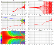
The first picture doesn't include any boundary effects, a LA in half space. T

The direct on-axis response is shown in the top graph. Its been equalized flat. The green line that wanders around it is the listening window average.
The next graph includes floor and ceiling reflections but only in the room response trace, which is the green line in the middle graph. Without the walls, it shows base boost at the low end and some "hash" in the high end. Notice what happens to HF in the bottom, directivity graph starting at 5 kHz, where driver spacing equals one wavelength.

The above is what you would expect with sufficient absorber on the walls near the LA.
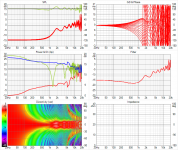
The next graph includes adds the front wall reflection, corresponding to mid wall placement.

We see a boundary null near 1 kHz, which speaks to how much absorber is required. I'm not sure how accurate this is. I believe the baffle doesn't figure into the calculation, just the distances from piston(s) to mic by both direct and reflection paths.
The final graph includes both walls as well as floor and ceiling. We get more bass and the two main nulls move a little.

How accurate are these sims? That remains to be seen. Recall Mark100 confirms need for wall absorbers. Also note (with relief) that the so called HF "hash" doesn't show up in his measurements.
Thanks, Wilbur.
Since some interest in minimizing boundary effects, lets see what we can learn from Vituix simulation. In these pictures, I am using 1 degree resolution directivity data produced by Vituix diffraction tool. IIRC its piston directivity and its needed here because I only measured to 10 degrees and Vituix doesn't interpolate. All 32 drivers are within 27 degrees and once out past 10 degrees, HF falls off rapidly so I need the 1 degree data for any kind of accuracy..
The first picture doesn't include any boundary effects, a LA in half space. T
The direct on-axis response is shown in the top graph. Its been equalized flat. The green line that wanders around it is the listening window average.
The next graph includes floor and ceiling reflections but only in the room response trace, which is the green line in the middle graph. Without the walls, it shows base boost at the low end and some "hash" in the high end. Notice what happens to HF in the bottom, directivity graph starting at 5 kHz, where driver spacing equals one wavelength.
The above is what you would expect with sufficient absorber on the walls near the LA.
The next graph includes adds the front wall reflection, corresponding to mid wall placement.
We see a boundary null near 1 kHz, which speaks to how much absorber is required. I'm not sure how accurate this is. I believe the baffle doesn't figure into the calculation, just the distances from piston(s) to mic by both direct and reflection paths.
The final graph includes both walls as well as floor and ceiling. We get more bass and the two main nulls move a little.
How accurate are these sims? That remains to be seen. Recall Mark100 confirms need for wall absorbers. Also note (with relief) that the so called HF "hash" doesn't show up in his measurements.
Attachments


Last edited:
nc535, that's some awesome stuff..many thx.
You're convincing me I need to learn Vituix.
At this point, the best sound I've achieved from mine is freestanding, a few feet out of the corners and with a sub.
The turnback on mine, from the baffle to the wall corners is 4.5", which I'm finding very difficult to dampen. Glad you're closer into the corner.
Nice work and great choice of drivers! My experience with my LA mirrors mark100. The best measurements/sound I'm getting are several feet from the wall free standing but I've pushed them a bit further into the corners. I didn't make my cabs to go into the corners so maybe I was not able to get them close enough.
I eqed them flat to 25 hz the other day and the presentation is really great. For my low SPL listening they work really well. With the subs integrated they take on that heft and effortless of the low end but there is something different in presentation between the 2.
I'm re-reading your Synergy thread. Cool projects!
first look at boundary interference
The rest of the hardware didn't come yesterday so I took a look at the boundary interference issues.
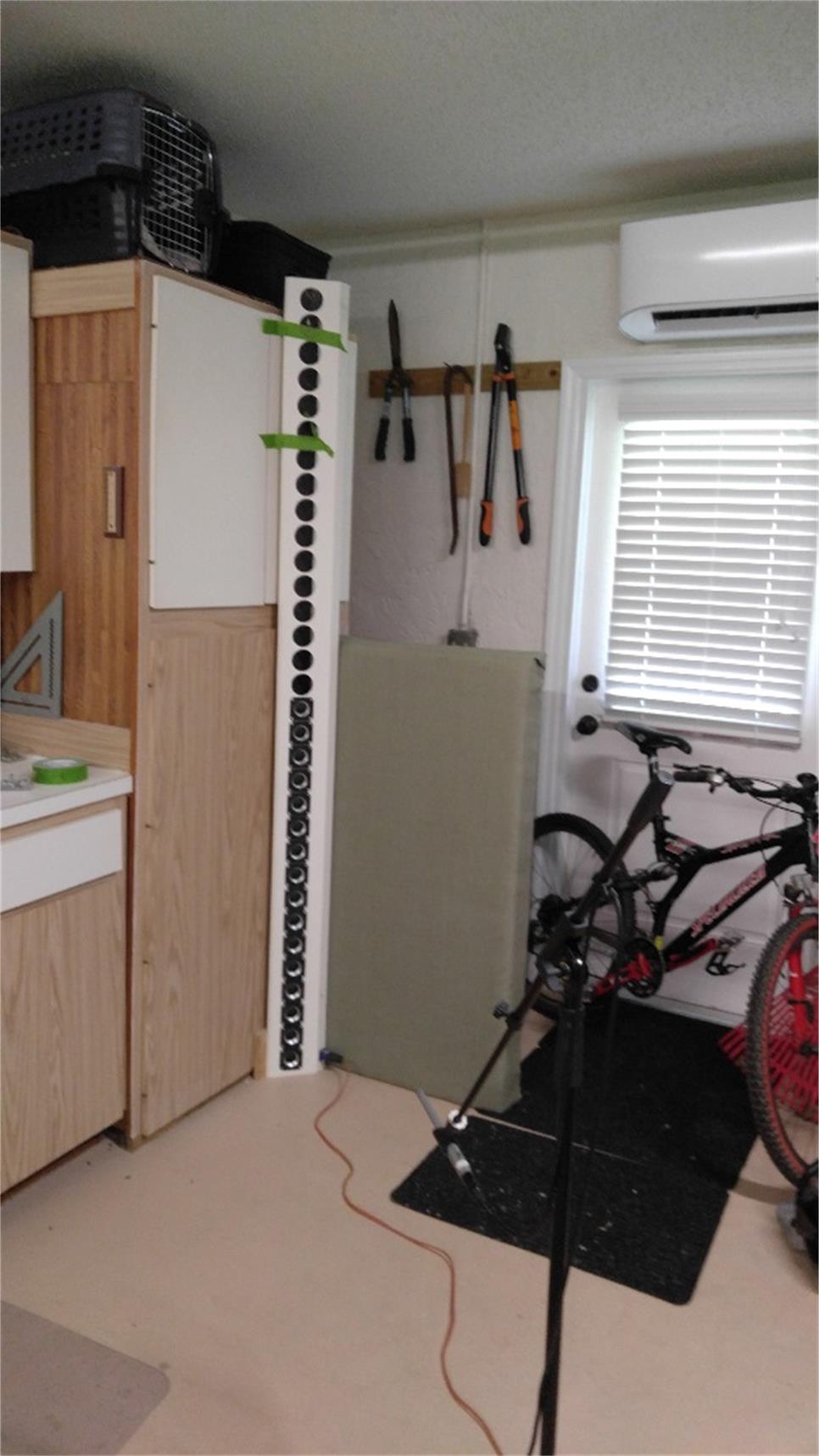
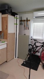
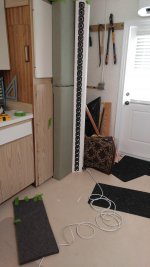
Here is the measurement environment:
and here is the measurement:
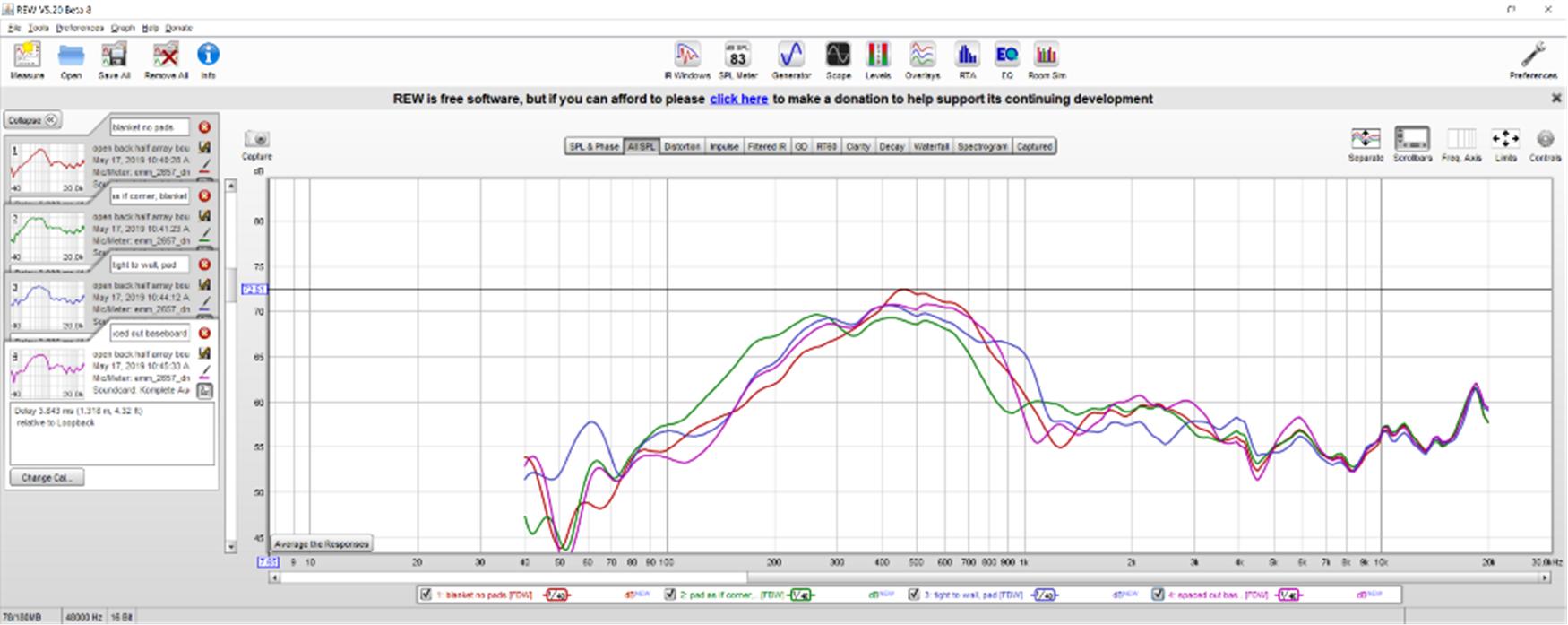
I measured with and without the blanket in front of the array (planning .5" thick felt) and the rigid fiberglass pad in back of it. The reason it looks so clean is my default 5 cycle FDW.
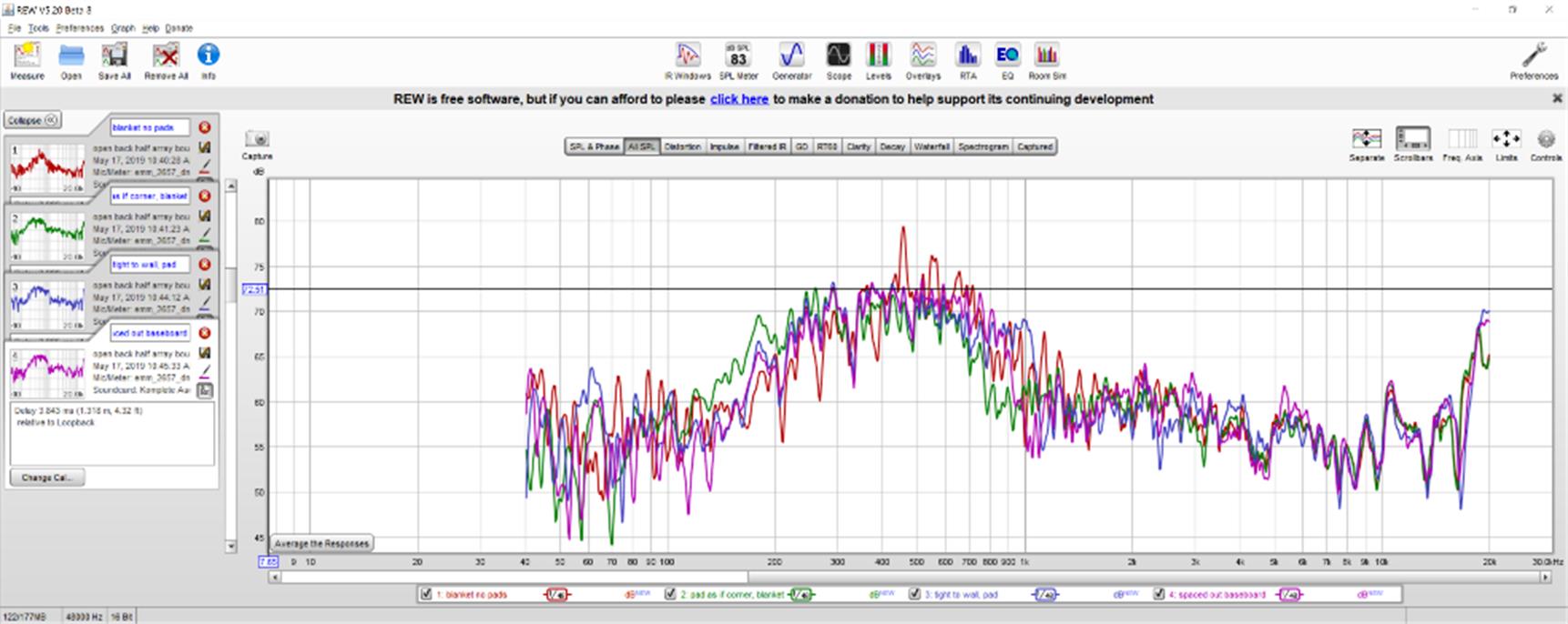
Here are the same measurements without the FDW:
I was feeling really good until I realized I had FDW on but even so I don't see and major boundary nulls, which is very encouraging. Given the environment and the open back on the cabinet, I really can't say more.
The rest of the hardware didn't come yesterday so I took a look at the boundary interference issues.
Here is the measurement environment:
and here is the measurement:
I measured with and without the blanket in front of the array (planning .5" thick felt) and the rigid fiberglass pad in back of it. The reason it looks so clean is my default 5 cycle FDW.
Here are the same measurements without the FDW:
I was feeling really good until I realized I had FDW on but even so I don't see and major boundary nulls, which is very encouraging. Given the environment and the open back on the cabinet, I really can't say more.
Attachments

 . Reading along since the start.
The rest of the hardware didn't come yesterday so I took a look at the boundary interference issues.
Here is the measurement environment:

and here is the measurement:

I measured with and without the blanket in front of the array (planning .5" thick felt) and the rigid fiberglass pad in back of it. The reason it looks so clean is my default 5 cycle FDW.
Here are the same measurements without the FDW:

I was feeling really good until I realized I had FDW on but even so I don't see and major boundary nulls, which is very encouraging. Given the environment and the open back on the cabinet, I really can't say more.
Compare these room response curves to the measurements posted today and you will see the Vituix prediction is highly pessimistic. I think the method Kimmosto uses breaks down when the baffle is so close to the boundary. When you have the array well away from the wall, the distance to the wall is much greater than the baffle width, which might be an implicit assumption in the method. I will have to repeat the experiment for the array out in the room.
closed the back, stuffed a rag in the front to seal off the missing drivers, hooked up a sub, and started listening. This is too much fun! I may never get back to wiring up drivers")
I like it
First full array measurements
The first cabinet is fully populated and here are some of the first measurements taken up against the garage door where 4" girders for hurricane protection keep the driver center roughly 6.5" from the door surface.
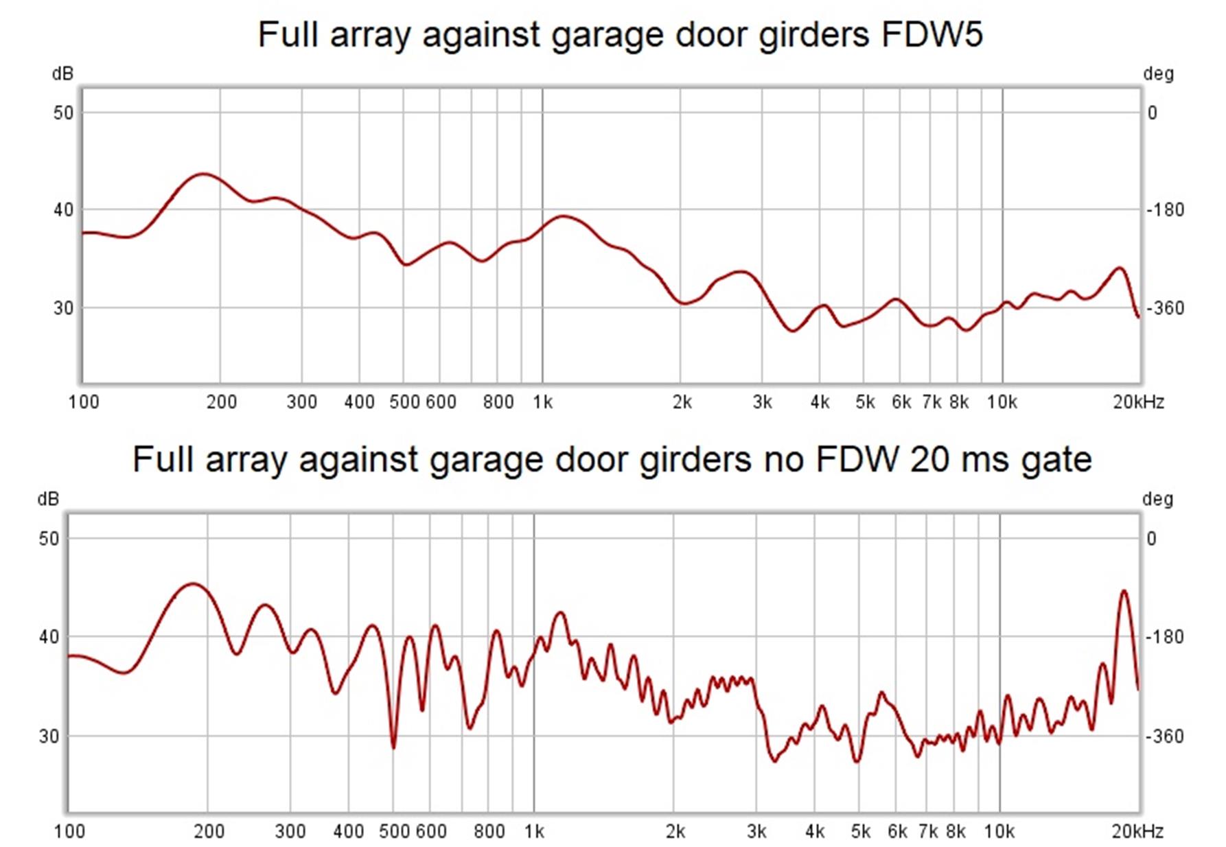
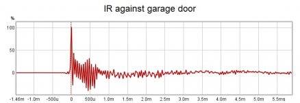
Should you ask, the impulse response is a mess with either ringing or early reflections that I have to debug. I have yet to stuff the cabinet with damping material so that might be part of the problem. Its as encouraging to see how nice the FR is with the FDW applied as it is concerning to see the impulse response. It might be an equipment problem as I had similar ringing in my Synergy horn measurements

The first cabinet is fully populated and here are some of the first measurements taken up against the garage door where 4" girders for hurricane protection keep the driver center roughly 6.5" from the door surface.
Should you ask, the impulse response is a mess with either ringing or early reflections that I have to debug. I have yet to stuff the cabinet with damping material so that might be part of the problem. Its as encouraging to see how nice the FR is with the FDW applied as it is concerning to see the impulse response. It might be an equipment problem as I had similar ringing in my Synergy horn measurements
Attachments

Today I stuffed the cabinet with fiberglass and then put the array up against 4" thick fiberglass absorber pads.
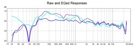
Here you can see improvements in raw response with the absorber taken at 3m. Tne nearby sidewall doesn't seem to be a problem. Teal is yesterday's result against garage door without any absorption. Blue is the EQed response.
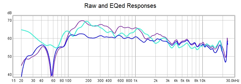
I did a not so quick manual EQ using PEQs. JRiver gave me a hard time so I revived my MiniDSP and amp from the Synergy project and got that going. This EQ has 9 db of bass boost. I'm planning to cross to subs at 80-100 Hz.
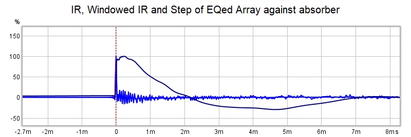
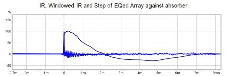
You can see the ringing is still in the IR, but not in the windowed IR, window defined by 5 cycle FDW. So the IR really is ringing and not due to any EQ filtering as the ringing appears in the raw responses also. What could make it ring?
Could it be low damping factor due to 8 drivers in series? I don't want to rewire the array only to find that wasn't the cause. Perhaps I could put some R in series with the amp and see if it gets worse. But I also had this ringing in my Synergy project so perhaps its something in the sound card.
Here you can see improvements in raw response with the absorber taken at 3m. Tne nearby sidewall doesn't seem to be a problem. Teal is yesterday's result against garage door without any absorption. Blue is the EQed response.
I did a not so quick manual EQ using PEQs. JRiver gave me a hard time so I revived my MiniDSP and amp from the Synergy project and got that going. This EQ has 9 db of bass boost. I'm planning to cross to subs at 80-100 Hz.
You can see the ringing is still in the IR, but not in the windowed IR, window defined by 5 cycle FDW. So the IR really is ringing and not due to any EQ filtering as the ringing appears in the raw responses also. What could make it ring?
Could it be low damping factor due to 8 drivers in series? I don't want to rewire the array only to find that wasn't the cause. Perhaps I could put some R in series with the amp and see if it gets worse. But I also had this ringing in my Synergy project so perhaps its something in the sound card.
Attachments
Last edited:
Wonderful suggestion. I've got many such measurements already from my driver eval.
... timeout....
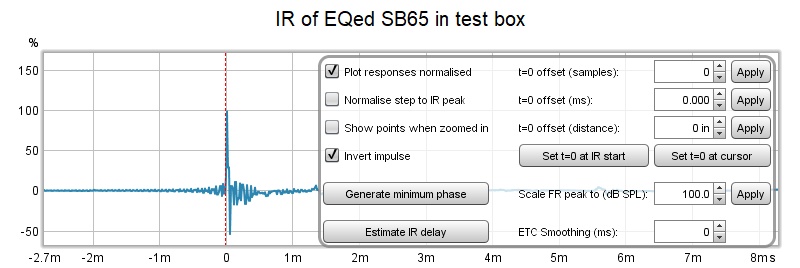
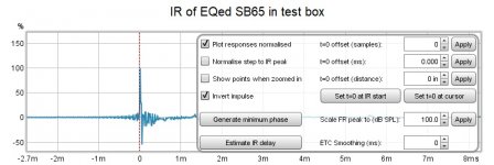
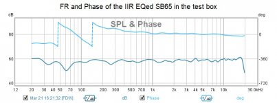
So it rings in the test box with a different amp; even has some pre-ringing...
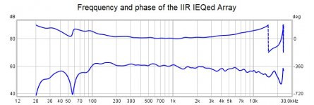
and just to complete the record:
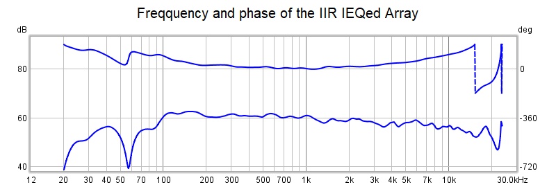
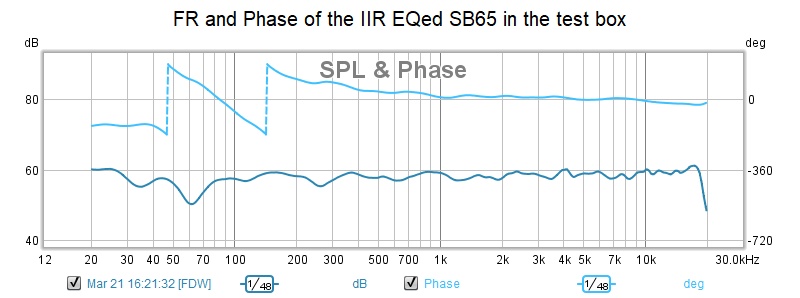
(apologies for the 20 db/div but the latest REW does that to me; I'm looking at them at 4 db/div. No matter, when I switch to FIR auto EQ it will be much smoother)
Notice the relatively flat phase without use of FIR
... timeout....
So it rings in the test box with a different amp; even has some pre-ringing...
and just to complete the record:
(apologies for the 20 db/div but the latest REW does that to me; I'm looking at them at 4 db/div. No matter, when I switch to FIR auto EQ it will be much smoother)
Notice the relatively flat phase without use of FIR
Attachments
- Home
- Loudspeakers
- Full Range
- Full range line array for wall or corner placement