KImmosto has generously put some effort into allowing me to simulate large numbers of drivers to make sure we're not missing anything with the usual 25 plus floor and ceiling reflections in the room response tab. With the changes, I can get 75 drivers plus their floor and ceiling reflections.
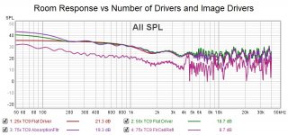
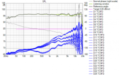
I've done a similar plot before showing equalized response vs number of drivers but I realized that the driver response and its EQ obscure the effect of adding more drivers and images. Here is a look with point sources at the 84mm TC9 spacing.
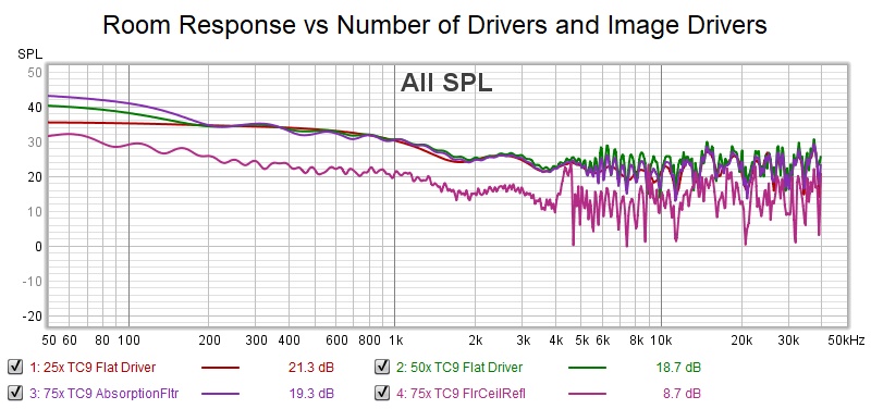
The red trace is the 25 driver array whose response we want to predict standing alone in free space. The green trace adds the floor image driver response to the direct drivers. The overlaying purple traces has both floor and ceiling image drivers combining with the direct driver response.
The purple trace below the others is will all 75 drivers enabled along with floor and ceiling reflections in the room response tab.
The difference in level is an artifact of some kind. I'm not sure how legitimate it is to mix image drivers with reflections calculated by another method from virtual floor and ceiling locations (+ & - 3.3m in this case)
I've done a similar plot before showing equalized response vs number of drivers but I realized that the driver response and its EQ obscure the effect of adding more drivers and images. Here is a look with point sources at the 84mm TC9 spacing.
The red trace is the 25 driver array whose response we want to predict standing alone in free space. The green trace adds the floor image driver response to the direct drivers. The overlaying purple traces has both floor and ceiling image drivers combining with the direct driver response.
The purple trace below the others is will all 75 drivers enabled along with floor and ceiling reflections in the room response tab.
The difference in level is an artifact of some kind. I'm not sure how legitimate it is to mix image drivers with reflections calculated by another method from virtual floor and ceiling locations (+ & - 3.3m in this case)
Attachments
The chart I have not shown yet are the sitting/standing comparisons.
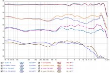
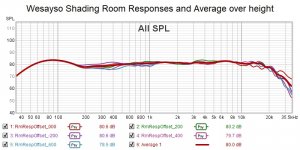
I've used psychoacoustic smoothing on these in-room results, as neither graph, be it unshaded or shaded, provides excellent results. Looking for balance here:

Obviously the shaded array will sound darker, while the unshaded array will sound a little brighter when standing up. Both show a maximum deviation of 5 dB between 100 Hz and 10 KHz.
This was the biggest compromise for me that I was willing to make. Neither is perfect, but I think it is still acceptable for the overall gain you get at seated listening positions to make this compromise.
At a distance of 4 meter the shaded array is showing a more even response while the unshaded version remains bright. However at a more distinct angle
the unshaded array will have an advantage in extension.
(under this specific angle of 25 degree, at 4 meter distance, the shaded version looks like an almost perfect 12 dB/octave roll off at 6 KHz)
The 1700 mm height was chosen because my ear is at that level standing up") .
.
I've used psychoacoustic smoothing on these in-room results, as neither graph, be it unshaded or shaded, provides excellent results. Looking for balance here:
Obviously the shaded array will sound darker, while the unshaded array will sound a little brighter when standing up. Both show a maximum deviation of 5 dB between 100 Hz and 10 KHz.
This was the biggest compromise for me that I was willing to make. Neither is perfect, but I think it is still acceptable for the overall gain you get at seated listening positions to make this compromise.
At a distance of 4 meter the shaded array is showing a more even response while the unshaded version remains bright. However at a more distinct angle
the unshaded array will have an advantage in extension.
(under this specific angle of 25 degree, at 4 meter distance, the shaded version looks like an almost perfect 12 dB/octave roll off at 6 KHz)
The 1700 mm height was chosen because my ear is at that level standing up
.Attachments
Last edited:
I copied W's shading and impedance compensation network to see how closee my simple EQ method could come to his results, which I thought was too much work, at least for simulation. It turns out I had to do a fair amount of work myself
First I was impressed by how well the compensation network works: the former impedance peak became a mere bump!
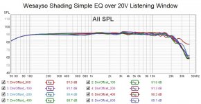
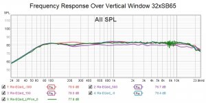
I tried equalizing the room response curve but this had the effect of magnifiying the combing that results from the floor and ceiling reflections. I decided instead to EQ to the Listening window and to cover the full sitting to standing range, I set the window to 20 degrees vertical. This was the result:
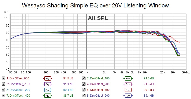
But that is just the axial response; what we hear is the room response which includes the floor and ceiling boundary support and affects the bass and midbass:
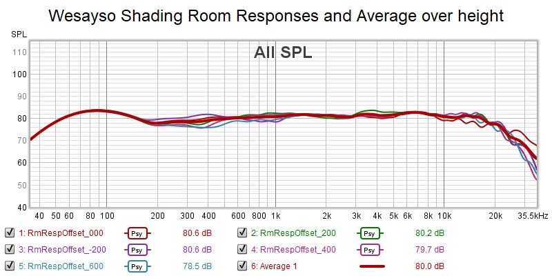
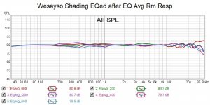
That is actually pretty good. Now let's equalize to the highly smoothed average of those room responses over -200 to +600 from 1.1m center
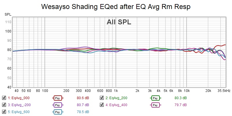
That is actually almost too good to be true so I wonder what I did wrong. I do see that I've overboosted the bass. I need to increase the slope of my high pass filter to restore the bass roll off to reasonability.
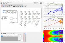
Here is the final Vituix screenshot
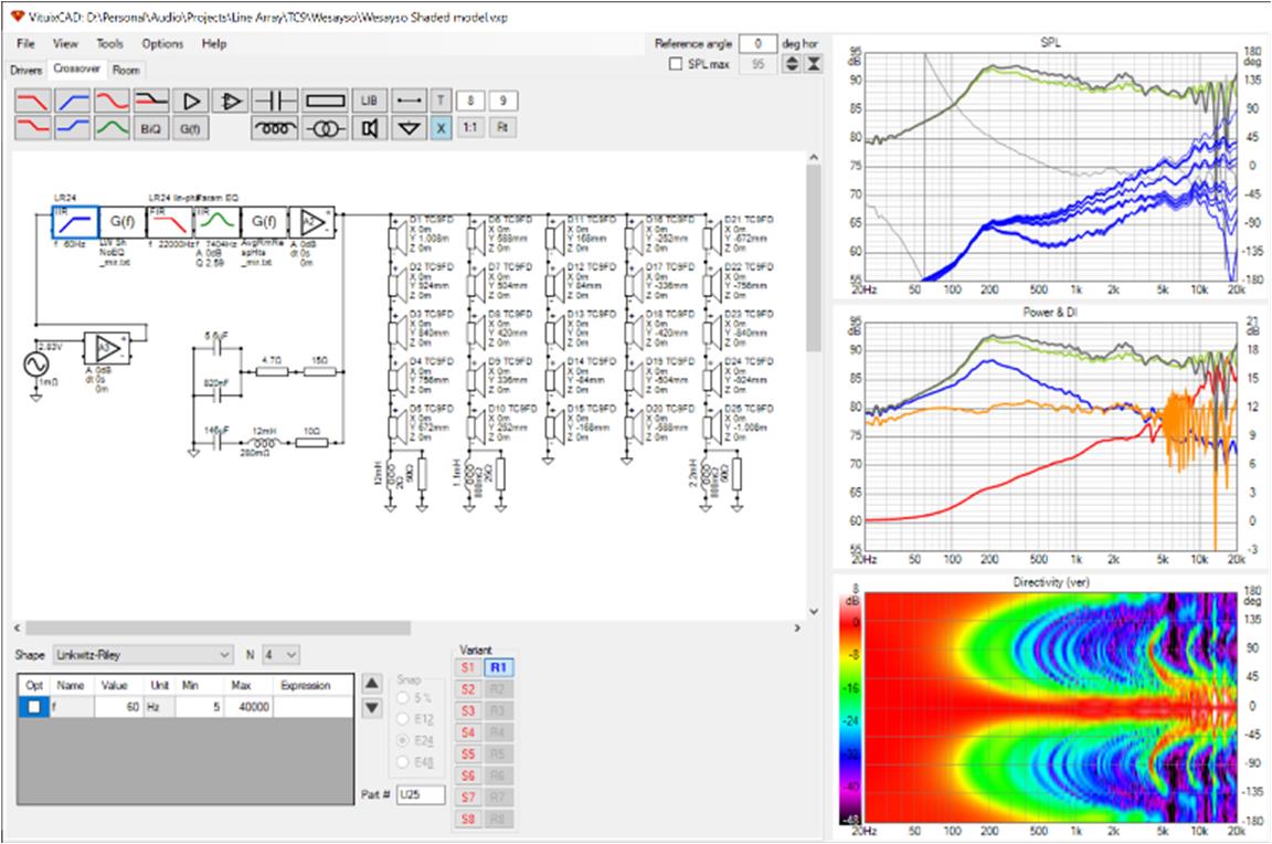
Each G(f) block in the schematic uses the Vituix calculator mirror process which is equivalent to impulse response inversion, like DRC does but without the sophisticated windowing. This works well in simulation but with real world measurements one would need the windowing to extract the desired response from the room effects. I make up for that to some extent by equalizing to 1/6th octave smoothed within Vituix and Psy smoothed on the imported average
I want to clarify that the first stage EQ here was to the Vituix Listening Window curve that is an average over the defined listening window: 15H, 20V. Thus it emulates using the average of multiple measurements. The 2nd stage EQ was also to an average of multiple simulated curves/measurements.
First I was impressed by how well the compensation network works: the former impedance peak became a mere bump!
I tried equalizing the room response curve but this had the effect of magnifiying the combing that results from the floor and ceiling reflections. I decided instead to EQ to the Listening window and to cover the full sitting to standing range, I set the window to 20 degrees vertical. This was the result:
But that is just the axial response; what we hear is the room response which includes the floor and ceiling boundary support and affects the bass and midbass:
That is actually pretty good. Now let's equalize to the highly smoothed average of those room responses over -200 to +600 from 1.1m center
That is actually almost too good to be true so I wonder what I did wrong. I do see that I've overboosted the bass. I need to increase the slope of my high pass filter to restore the bass roll off to reasonability.
Here is the final Vituix screenshot
Each G(f) block in the schematic uses the Vituix calculator mirror process which is equivalent to impulse response inversion, like DRC does but without the sophisticated windowing. This works well in simulation but with real world measurements one would need the windowing to extract the desired response from the room effects. I make up for that to some extent by equalizing to 1/6th octave smoothed within Vituix and Psy smoothed on the imported average
I want to clarify that the first stage EQ here was to the Vituix Listening Window curve that is an average over the defined listening window: 15H, 20V. Thus it emulates using the average of multiple measurements. The 2nd stage EQ was also to an average of multiple simulated curves/measurements.
Attachments
Last edited:
So what do you think about it? Do-able?
By the way, my impedance compensation was applied by measuring the results of my arrays and go from there.
First done by BYRTT with X-sim, fine-tuned after some baffle changes I did. in the sim I used an impedance curve of a single driver
that represented the average of my 25 drivers measured in my left channel. I could have picked the array curve but figured Virtuixcad
would form total impedance based on a single driver curve. They are pretty similar, but the correction is somewhat flatter with the true
array impedance curve. Just as a side note...
Last edited:
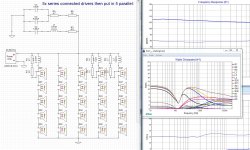
I think its very do-able and I'm in the midst of figuring out how to do it for my own array of 32 4-ohm drivers, whose relative fragility makes me wary. They are now wired in 4 parallel groups of 8 in series so I will just have to separate those chains midway.
I'm impressed at how flat the results of simulated multi-point measurements are. The keys, as you found, are an unshaded group of drivers that spans the target vertical window, and a tall vertical listening window for equalization to the listening window average. The 20 degrees I used seems to work well.
I have to deal with more groups and half the impedance level so tried bi-amping the array with 12 unshaded drivers on one amp and the remaining 20 outer drivers on a second amp. I then apply the passive shelf shading and equalize for sitting to standing vertical window. I then asked myself what if I low pass filtered the outer group of drivers? I found that the vertical window shrunk but the combing in the top octave and a half disappeared - except for that caused by the floor and ceiling reflection. It appears that I will be able to come up with a filter preset to optimize seated listening and it might be as simple as turning a 700 Hz linear phase low pass filter on.
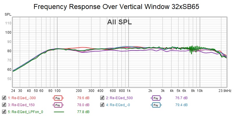
The green is with the low past filter enabled. It shows combing but its not smoothed. The others are PSY smoothed to hide their more severe combing.
So now I have to look at impedance compensation. The Zpeak now is quite tall!
I'm impressed at how flat the results of simulated multi-point measurements are. The keys, as you found, are an unshaded group of drivers that spans the target vertical window, and a tall vertical listening window for equalization to the listening window average. The 20 degrees I used seems to work well.
I have to deal with more groups and half the impedance level so tried bi-amping the array with 12 unshaded drivers on one amp and the remaining 20 outer drivers on a second amp. I then apply the passive shelf shading and equalize for sitting to standing vertical window. I then asked myself what if I low pass filtered the outer group of drivers? I found that the vertical window shrunk but the combing in the top octave and a half disappeared - except for that caused by the floor and ceiling reflection. It appears that I will be able to come up with a filter preset to optimize seated listening and it might be as simple as turning a 700 Hz linear phase low pass filter on.
The green is with the low past filter enabled. It shows combing but its not smoothed. The others are PSY smoothed to hide their more severe combing.
So now I have to look at impedance compensation. The Zpeak now is quite tall!
Attachments
I copied just the series RLC Zobel from W's schematic, tweaked values slightly, and pulled my resonant impedance peaks down nicely. The zobel doesn't affect the frequency response so I don't know if I will bother to implement them.
I had expected that the Zobel would affect the response of the passive shelf snubbers but now I see that to do this, I would have to put a separate zobel across each series connected driver string. Without these Zobels, the shelf shading filters have a peak in response at the resonant frequency, which actually helps the inductors in undoing the shading at low frequencies and a slight rise towards the high end that follows the driver impedance change. But the amplifier should have no trouble with the load and the equalization result will be the same with or without the zobels in place.
I had expected that the Zobel would affect the response of the passive shelf snubbers but now I see that to do this, I would have to put a separate zobel across each series connected driver string. Without these Zobels, the shelf shading filters have a peak in response at the resonant frequency, which actually helps the inductors in undoing the shading at low frequencies and a slight rise towards the high end that follows the driver impedance change. But the amplifier should have no trouble with the load and the equalization result will be the same with or without the zobels in place.
Attachments
I found a free download of Douglas Self's audio power amplifier design handbook and he had a lot to say about amplifiers driving speakers vs resistive loads.
The paragraph on driving the load of a single speaker is applicable because it would also apply to driving numbers of them in series parallel combination
that is the phase angle of the impedance
so perhaps the zobel does have some benefits despite not affecting the frequency response
The paragraph on driving the load of a single speaker is applicable because it would also apply to driving numbers of them in series parallel combination
Figures 8.37 – 8.39 are the distilled results of a very large number of simulations. Figure 8.38 shows that the gentle foothills of the impedance peak at bass resonance actually increase the peak instantaneous power stress on the output devices by 30%, despite the reduced current drawn. The most dangerous regions for the amplifi er are the sides of a resonance hump where the phase shift is the greatest. Peak dissipation only falls below that for an 8 Ω resistor (shown dotted) around the actual resonance peak, where it drops quickly to a quarter of the resistive case. Likewise, the increase in impedance at the HF end of the spectrum, where voice-coil inductance is significant, causes a more serious rise in peak dissipation to 50% more than the resistive case. The conclusion is that, for peak power, the phase angle is far more important than the impedance
magnitude.
that is the phase angle of the impedance
so perhaps the zobel does have some benefits despite not affecting the frequency response
Yes, I'd agree... the idea of it is that the amplifier only gets to see a resistive load.
Many would argue that it doesn't matter and that all well constructed amplifiers can easily deal with it. This may be true. I just opted to test it and pick whatever did sound 'better' to me. In how many cases do we actually run a driver straight through the impedance peak? I mean I do/did use it like that.
This 'better' in this case is highly subjective.
Many would argue that it doesn't matter and that all well constructed amplifiers can easily deal with it. This may be true. I just opted to test it and pick whatever did sound 'better' to me. In how many cases do we actually run a driver straight through the impedance peak? I mean I do/did use it like that.
This 'better' in this case is highly subjective
.
Last edited:
Given the cost and space requirements of inductors, that is a marginal benefit I'll likely pass on. In fact, when I lpriced the L's I had in my own shelf shaded array, I was persuaded to go back to looking at active shading solutions. I have a good 8 channel amp and I might as well use it. The bottom line is I will be able to have one preset for seated through standing listening and a second one optimized for seated and this for minimum additional cost out of pocket.
For my shading schematic I did not find the components that expensive.
The most expensive part is a 12 mH air coil, 1mm with 2.23 Ohm resistance.
12.0mH 1.00mm Air Core Wire Coil Rdc 2,230 Ohm | RumoH - Caps, Coils and Speakers
That's not amplifier money to me, I only need 2 of those. The resistors can be 10 watt, 2 in series for next to nothing. X-Sim tells me they see about 8 watt max, less than that if I use 2 in series even for the smaller ~ 25 Ohm value. (about 6 watt with 240 watt feeding the array)
The zobel I have already, but that has no relation to the shading needed here.

The most expensive part is a 12 mH air coil, 1mm with 2.23 Ohm resistance.
12.0mH 1.00mm Air Core Wire Coil Rdc 2,230 Ohm | RumoH - Caps, Coils and Speakers
That's not amplifier money to me
, I only need 2 of those. The resistors can be 10 watt, 2 in series for next to nothing. X-Sim tells me they see about 8 watt max, less than that if I use 2 in series even for the smaller ~ 25 Ohm value. (about 6 watt with 240 watt feeding the array)The zobel I have already, but that has no relation to the shading needed here.
Attachments
Last edited:
Recently I re-opened my SB65 array simulation intending to develop shading for it.
I have been using the Vituix calculator tool mirror process as the primary equalization method. For the unshaded array, it does a good job of flattening the phase as well as the magnitude of the frequency response:
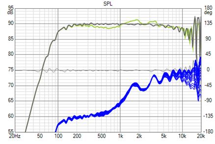
This is a great result for about 1 minute of effort without ever leaving Vituix.
But with shading, the phase is anything but flat and the step response not only falls short of ideal but has a curious shape:
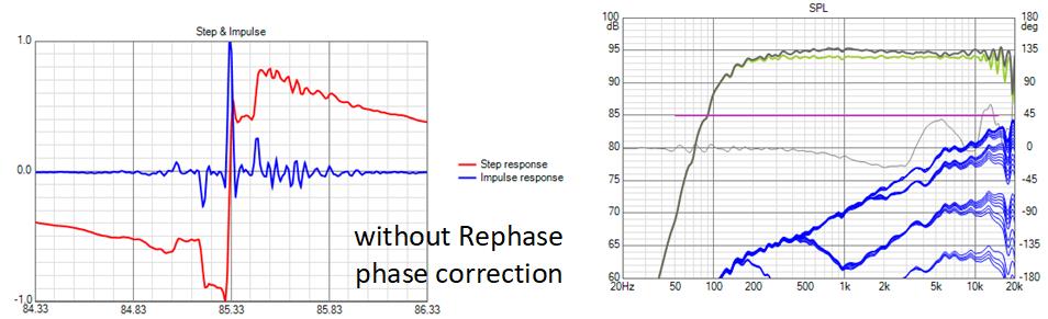
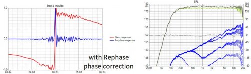
I wondered if REW calculator 1/A inversion would give me flat phase. It didn't! Therefore, I exported to Rephase and did manual phase correction there:

I can't explain why mirror doesn't work as well with shading as without. Is it a minimum phase issue? I would have thought shading would bring an array closer to minimum phase because it de-emphases the more distant contributors.
I have been using the Vituix calculator tool mirror process as the primary equalization method. For the unshaded array, it does a good job of flattening the phase as well as the magnitude of the frequency response:
This is a great result for about 1 minute of effort without ever leaving Vituix.
But with shading, the phase is anything but flat and the step response not only falls short of ideal but has a curious shape:
I wondered if REW calculator 1/A inversion would give me flat phase. It didn't! Therefore, I exported to Rephase and did manual phase correction there:
I can't explain why mirror doesn't work as well with shading as without. Is it a minimum phase issue? I would have thought shading would bring an array closer to minimum phase because it de-emphases the more distant contributors.
Attachments


How did you do the shading? They do look like almost square corners...
Here's my shading with inductor bypassed with resistor:

I'd say that's much more gradual. Messing with the shape of the shading is also messing up time arrival. The resulting IR will be the sum of the total. That's why I couldn't just use crossovers but reverted back to shading. As I have no passive means to correct for timing differences. This way the timing differences are subtle enough for DRC to fix.
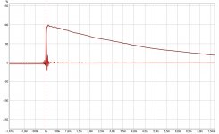
And the IR (as corrected with DRC-FIR):
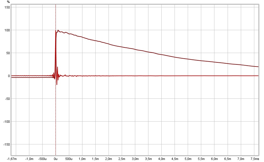
This should not be the most ideal result, as I switched out some resistor combinations, but the influence on the IR isn't that big.
Maybe a good moment to start using DRC for the corrections?
Here's my shading with inductor bypassed with resistor:
I'd say that's much more gradual. Messing with the shape of the shading is also messing up time arrival. The resulting IR will be the sum of the total. That's why I couldn't just use crossovers but reverted back to shading. As I have no passive means to correct for timing differences. This way the timing differences are subtle enough for DRC to fix.
And the IR (as corrected with DRC-FIR):
This should not be the most ideal result, as I switched out some resistor combinations, but the influence on the IR isn't that big.
Maybe a good moment to start using DRC for the corrections?
Attachments
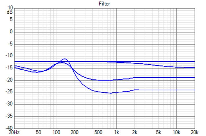
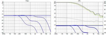
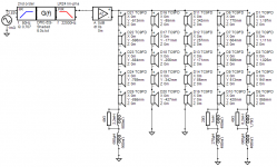
I'll show the shading schematic and the filter shape uncorrupted by driver response or equalization

Now that I'm active DSP weighted I have tremendous flexibility. The shelves are made with 2nd order linear phase shelf filters. I control steepness with Q and found steeper was better (phase/timing not withstanding) because it allowed each group to contribute over a wider range while being attenuated before its delta path phase shift exceeded 90 degrees. Using linear phase filters means there is no filter delay to add to the delta path delay. I see your more gradual mechanism has nice phase; there definitely is something going on with phase in my circuit and I'm only just coming to grips with it.
To optimize for seated position, I enable the low pass filters now shorted out. This reduces the combing in the top octave without much effect elsewhere.
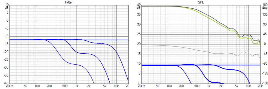
The array center is close enough to my seated (at desk) ear height not to matter. To optimize over seated through standing I need to move the mic up, haven't decided how far yet.
Now that I'm active DSP weighted I have tremendous flexibility. The shelves are made with 2nd order linear phase shelf filters. I control steepness with Q and found steeper was better (phase/timing not withstanding) because it allowed each group to contribute over a wider range while being attenuated before its delta path phase shift exceeded 90 degrees. Using linear phase filters means there is no filter delay to add to the delta path delay. I see your more gradual mechanism has nice phase; there definitely is something going on with phase in my circuit and I'm only just coming to grips with it.
To optimize for seated position, I enable the low pass filters now shorted out. This reduces the combing in the top octave without much effect elsewhere.
The array center is close enough to my seated (at desk) ear height not to matter. To optimize over seated through standing I need to move the mic up, haven't decided how far yet.
Attachments
Curious. I first changed from linear phase to IIR shelf filters and then changed the filter Q from 1 to 0.25. With both changes I still had the same/similar unflat phase after mirroring. So I'm going to stick with my original (for now) and the separate phase correction step.
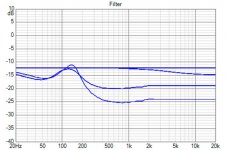
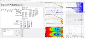
Taking the Shelf-shade circuit one notch up seems promising...
Still need to work out the components, the upper FR end gets the most benefits...

Basically it helps to counter the rising impedance of the driver which made the shelf correction less effective. Still all passive.
I'll show more once I figure out what actual numbers to use. Some components are still a little off (wrong resistance figures on inductors etc.).
Looking for trends on what it does, this could proof to be a valid addition.
Still need to work out the components, the upper FR end gets the most benefits...
Basically it helps to counter the rising impedance of the driver which made the shelf correction less effective. Still all passive.
I'll show more once I figure out what actual numbers to use. Some components are still a little off (wrong resistance figures on inductors etc.).
Looking for trends on what it does, this could proof to be a valid addition.
Attachments
- Home
- Loudspeakers
- Full Range
- Full range line array for wall or corner placement