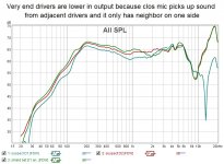
Would a polarity swap on 1 or more drivers cause a combined response like your seeing?
yes it could and I suspected that until I took the data that led to my previous post.
Take a 12v battery (e.g from a hand tool) and hook it up to the speaker and observe from the side that all pop the same direction. Thats how I checked that I wired the whole thing correctly.
Post #55 My FR10HM corner-ceiling-floor-array
//
Post #55 My FR10HM corner-ceiling-floor-array
//
Last edited:
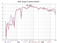
well with both arrays measuring almost identically, there is no longer reason to suspect a problem. The real problem was the first array simply didn't have enough stuffing in it to absorb lengthwise reflections off the ends. Along the way to discovering that, I found and fixed:
* a physically damaged driver
* a failed glue joint
* a bad crimp resulting in a loose, likely high resistance connection
* a physically damaged driver
* a failed glue joint
* a bad crimp resulting in a loose, likely high resistance connection
The next challenge is taming the room enough for DSP to be able to do its thing.
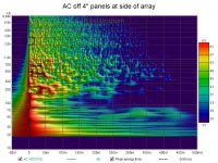
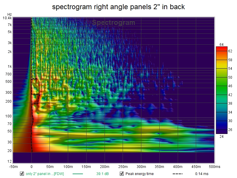
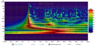
A spectrogram shows what I'm up against
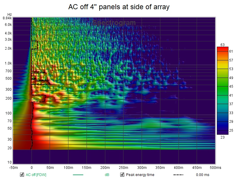
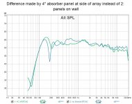
Placing a 4" panel against the side of the array tamed that ~200 hz null enough to equalize. Perhaps a panel at the first reflection point would do the same thing.
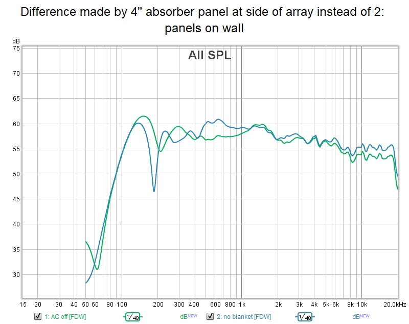
The rest of the reflections above 100 hz seem to be end to end reflections, which has me thinking about ways to attach absorber to the garage door.
A spectrogram shows what I'm up against
Placing a 4" panel against the side of the array tamed that ~200 hz null enough to equalize. Perhaps a panel at the first reflection point would do the same thing.
The rest of the reflections above 100 hz seem to be end to end reflections, which has me thinking about ways to attach absorber to the garage door.
Attachments
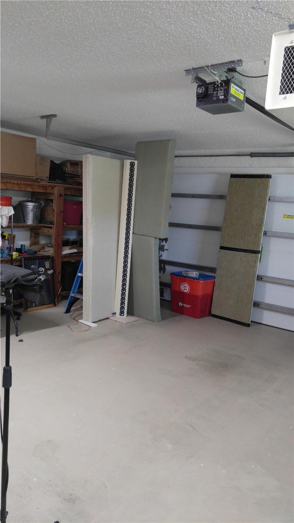
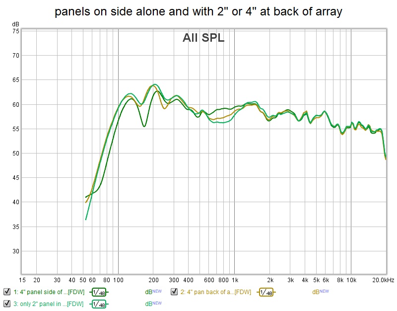
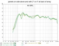
I got braver on the left side and found an absorber panel configuration that works well. The 2" panel leaning against the garage wall works just as well as the precariously stacked 4" panels so that is what I will use.
as before, it cleaned up the FR to where it can be EQed
(this is with an 18 ms gate plus FDW5)
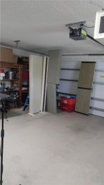
but it also cleaned up the spectrogram
where you can see the reason for the 18 ms gate - the reflection coming from the far end of the garage at about 20 ms.
So it looks like I need to make a pair of right angle absorber panel stands on casters for use out here in the garage/man cave
as before, it cleaned up the FR to where it can be EQed
(this is with an 18 ms gate plus FDW5)
but it also cleaned up the spectrogram
where you can see the reason for the 18 ms gate - the reflection coming from the far end of the garage at about 20 ms.
So it looks like I need to make a pair of right angle absorber panel stands on casters for use out here in the garage/man cave
Attachments

i fastened the 3 panels together today to make a fairly robust corner absorber which works quite well out in the room, as we've seen, The base with casters is still to be done but I have a scrap of plywood ready to go.
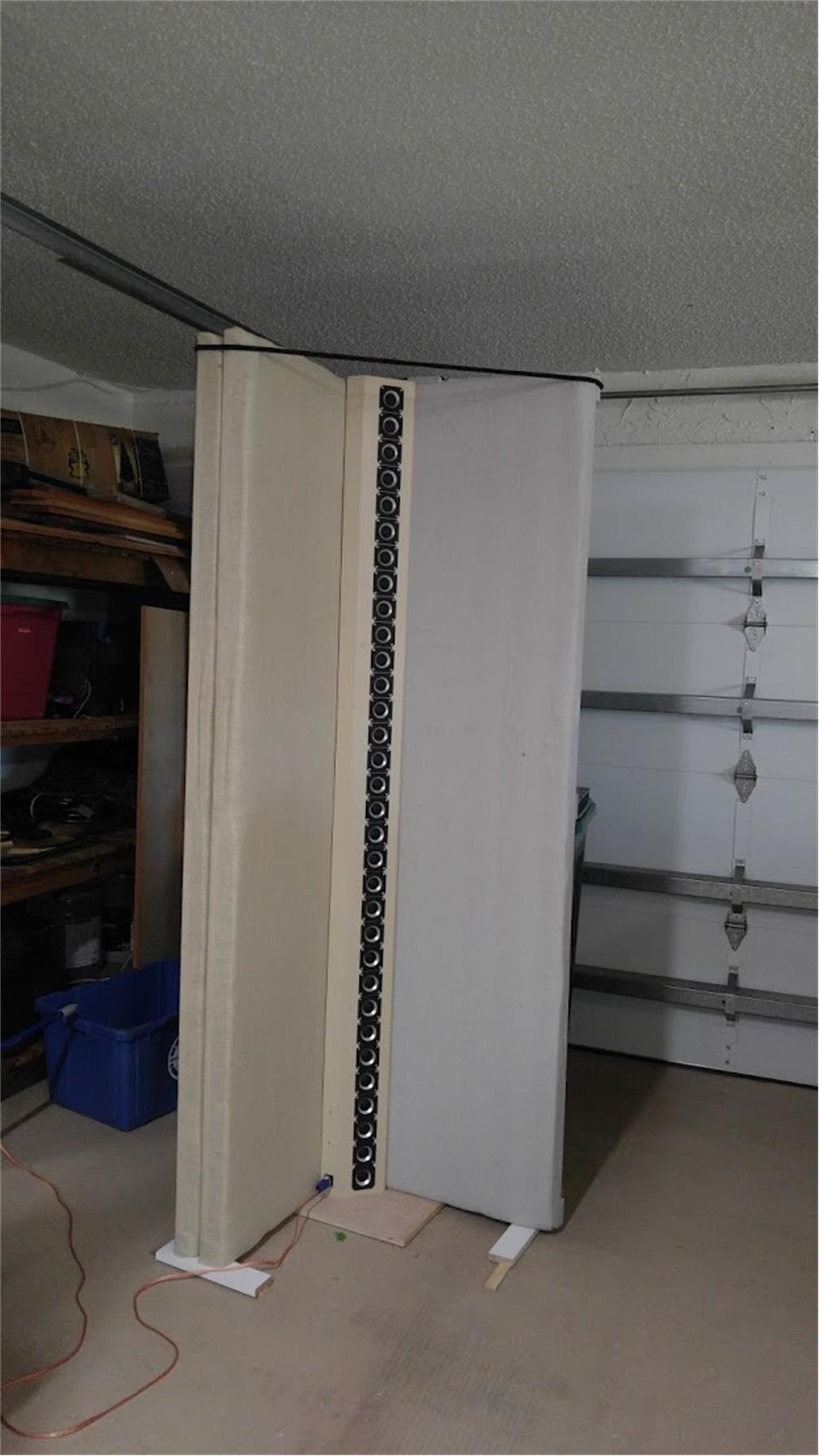
I had no more of the expensive acoustic fabric used on the first two panels so I covered the third with a $15 light painter's canvas dropcloth from Home Depot. Too bad the colors don't match.
I had no more of the expensive acoustic fabric used on the first two panels so I covered the third with a $15 light painter's canvas dropcloth from Home Depot. Too bad the colors don't match.
Attachments

Now its time for DSP. Here are my miniDSP pre-EQ results. Just hi and low shelf filters and a low Q PEQ
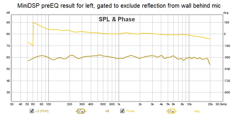
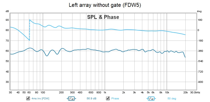
without the gate, 100-220hz gets bumpy. This is just the single 15" woofer behind the corner absorber and to the left

With this I see the main treatment problem for this room - the wall behind the mic. This wall consists of re-purposed kitchen cabinets so I would have to attach any absorption to cabinet doors.
without the gate, 100-220hz gets bumpy. This is just the single 15" woofer behind the corner absorber and to the left
With this I see the main treatment problem for this room - the wall behind the mic. This wall consists of re-purposed kitchen cabinets so I would have to attach any absorption to cabinet doors.
Attachments

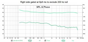
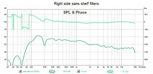
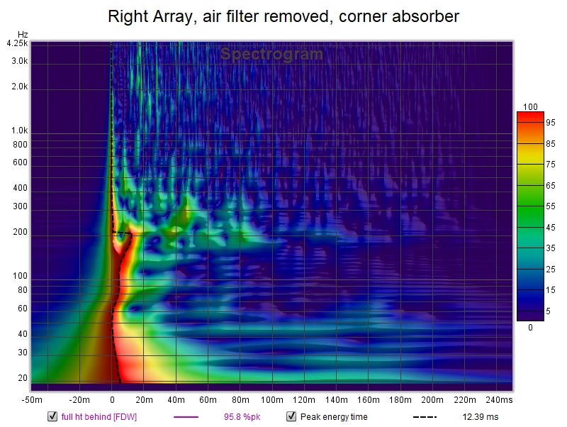
The right side isn't as pretty. These measurements have no EQ and, I see belatedly, with the woofer off.. The 200 Hz dip is back partially suppressed by a 4" pad behind the array.
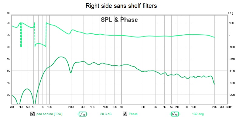
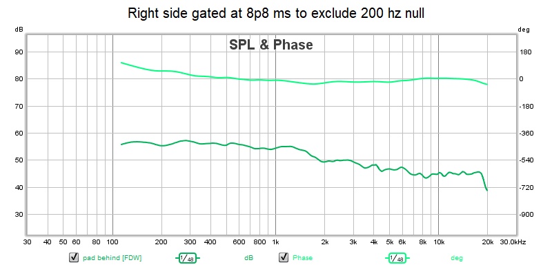

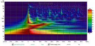
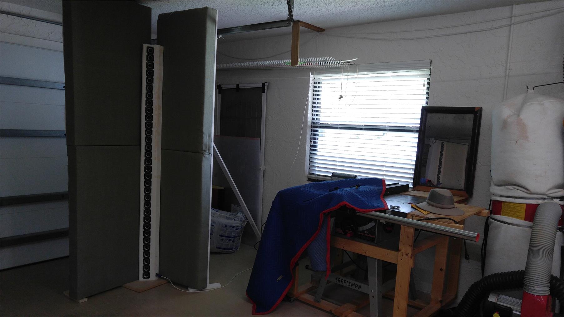
The spectrogram shows issues below 300 Hz. Why would it be different from the other side, other than that the woofer is off? Pretty wide time distribution of energy 100-300 Hz. Possibly due to the air filter I've got hanging down in front of the array on this side.
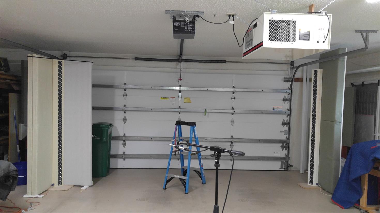
The perspective makes it look like the filter is out of the way but its halfway between the mic and the array and comes down to the level of the 3rd or 4th driver from the top of the array. With a little work, I can mount the filter tight to the ceiling... and then pad its bottom surface
Notice also the 8' tall absorber I made tacking two 2'x4' pads together - so now its too tall to fit under the garage door when its open. I got the best results when it was behind the array rather than at its side.
The spectrogram shows issues below 300 Hz. Why would it be different from the other side, other than that the woofer is off? Pretty wide time distribution of energy 100-300 Hz. Possibly due to the air filter I've got hanging down in front of the array on this side.
The perspective makes it look like the filter is out of the way but its halfway between the mic and the array and comes down to the level of the 3rd or 4th driver from the top of the array. With a little work, I can mount the filter tight to the ceiling... and then pad its bottom surface
Notice also the 8' tall absorber I made tacking two 2'x4' pads together - so now its too tall to fit under the garage door when its open. I got the best results when it was behind the array rather than at its side.
Attachments
Last edited:
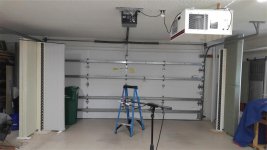
Realized i could relocate the air filter really easily and so did that.
Rigged corner absorpion around the array and got an improved spectrogram

So where is that ~11 ms reflection coming from?
the speaker is
4'3" from the front wall,
5'3" from the near side wall
the mic is 11', 10' and 9' from various back wall surfaces
Those distances point to a side wall reflection but its the left hand array visible in the mirror in this picture
Rigged corner absorpion around the array and got an improved spectrogram
So where is that ~11 ms reflection coming from?
the speaker is
4'3" from the front wall,
5'3" from the near side wall
the mic is 11', 10' and 9' from various back wall surfaces
Those distances point to a side wall reflection but its the left hand array visible in the mirror in this picture
Attachments


...Rigged corner absorpion around the array and got an improved spectrogram...
Nice was my first thought
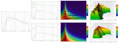
") well up until response was under deeper compare study using smooth reference file and by trace your amplitude response over in VirtuixCad then exported IR and made a 100 % minimum phase timing belonging to that response, and now it turns out that amplitude response is too rough to interpret in time domain in that we get natural wiggles from -20 mS up to +32 mS see below graphs where study is based on 48kHz rate and the smooth bandpass is a 4th order HP LR at 100Hz and LP is 2nd order BW at 25kHz.
well up until response was under deeper compare study using smooth reference file and by trace your amplitude response over in VirtuixCad then exported IR and made a 100 % minimum phase timing belonging to that response, and now it turns out that amplitude response is too rough to interpret in time domain in that we get natural wiggles from -20 mS up to +32 mS see below graphs where study is based on 48kHz rate and the smooth bandpass is a 4th order HP LR at 100Hz and LP is 2nd order BW at 25kHz.Attachments
Impressive job of reverse engineering...
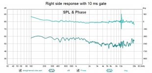
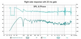
Well, its nicer than it was, believe me. And it is indeed nice if you gate out that 11 ms reflection. Here is the response with 10 and 20 ms gates
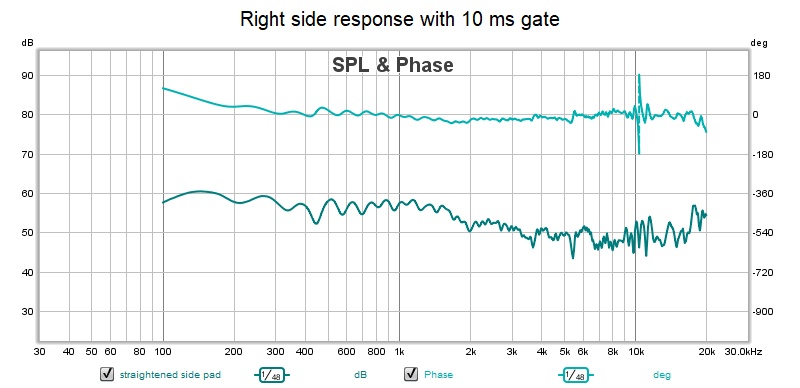
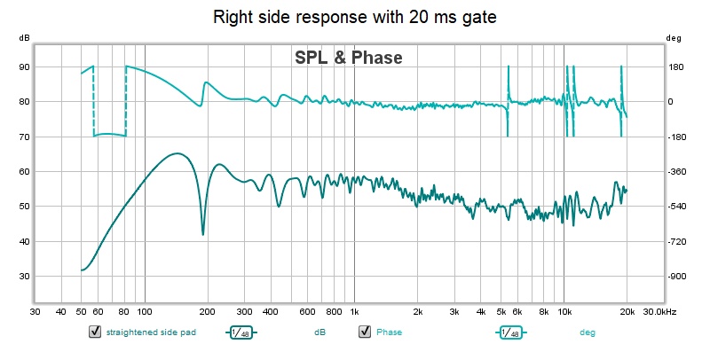
My question, not completely rhetorical, is will my brain filter out those 10+ ms reflections. By most standards, they are late. And should I therefore equalize to the gated measurement or do a room correction?
I would of course prefer to find the source of those reflections and kill them there. Got a box of roxul coming hopefully tomorrow...
Well, its nicer than it was, believe me. And it is indeed nice if you gate out that 11 ms reflection. Here is the response with 10 and 20 ms gates
My question, not completely rhetorical, is will my brain filter out those 10+ ms reflections. By most standards, they are late. And should I therefore equalize to the gated measurement or do a room correction?
I would of course prefer to find the source of those reflections and kill them there. Got a box of roxul coming hopefully tomorrow...
Attachments
So where is that ~11 ms reflection coming from?
11 ms? you mean at ~200 Hz? The hole before it is the real problem. Meaning you have some build-up of energy that crates that hole, making the loudest part come in just after that. You can see the reflective surface at 400 Hz too, as a parallel ridge beside the main signal all the way up to 800 Hz. That's the timing you need to figure out.
It's that reflection that messes up your result.
Thanks. I was looking but not seeing.
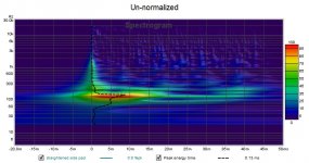
That hole is the null and it has to be at just over 5 ms, half the period of the null at just under 200 Hz. It can't be anywhere else for that null.
But the 200 hz energy is spread out in time. Else there wouldn't be any around after the null passes by. But the intensity is normalize; perhaps that is misleading us.
Attachments
- Home
- Loudspeakers
- Full Range
- Full range line array for wall or corner placement