tryed out the filters
Oh, so you want to know if I'm a bass head") Yes I am. Haven't listened much though due to time and family constraints
Yes I am. Haven't listened much though due to time and family constraints
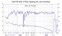
...wondering why the treble drooping so severely
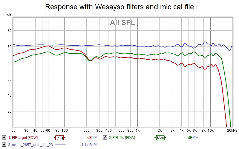
I see I'm really missing the cal file but I'm also confused because I see that same 4 khz undulation in my own measurement that uses the cal file
No hurry, the zips are firmly attached
I am curious though, which one of these files you'd like best.
Oh, so you want to know if I'm a bass head
Yes I am. Haven't listened much though due to time and family constraints...wondering why the treble drooping so severely
I see I'm really missing the cal file but I'm also confused because I see that same 4 khz undulation in my own measurement that uses the cal file
Attachments
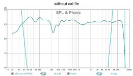
Now I understand. Since DRC corrected it smooth without mic cal file. I will only measure it smooth w/o cal file but I hear it unsmooth.
What i need to do is to make a measurement with cal file enabled and then create a filter that just smooths out the cal file wrinkles and then REW* that with the DRC filter
What i need to do is to make a measurement with cal file enabled and then create a filter that just smooths out the cal file wrinkles and then REW* that with the DRC filter
my attempts to replace the missing mic cal file by convolution came to nought. Neither my DRC templates nor REW auto EQ would follow the undulations. So I added 4 PEQs in JR and got within +/- 1db of the original FIR-file without the cal file enabled which, via a double negative, was my target.
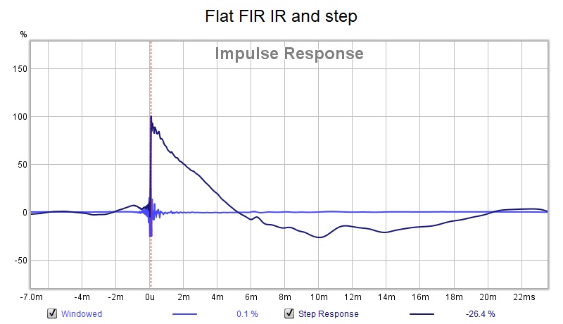
My measurements are all with the flat FIR tile but I'm listening to the FIR-target because it had too much treble and I like the bass boost. Don't want to pause the listening for another measurement (and these FRs are FDW15)

Wesayso's process seems like magic to me. I can't come close to duplicating these results on my own. Thanks, Ron, for all the help!
My measurements are all with the flat FIR tile but I'm listening to the FIR-target because it had too much treble and I like the bass boost. Don't want to pause the listening for another measurement (and these FRs are FDW15)
Wesayso's process seems like magic to me. I can't come close to duplicating these results on my own. Thanks, Ron, for all the help!
Attachments
Wesayso's process seems like magic to me. I can't come close to duplicating these results on my own. Thanks, Ron, for all the help!
It's black magic
. I had to undergo several rituals to get this far .Does that target file sound any good? I can show you how I did it but we would have to meet at the Crossroads
.YouTube
Last edited:
I've been listening to that target and loving it.
I was just looking at your incantations - command line options in your custom.bat (sic)
Found it way back in your thread, went looking so I wouldn't have to ask but that is one long command line to pick apart and understand.
I was just looking at your incantations - command line options in your custom.bat (sic)
Found it way back in your thread, went looking so I wouldn't have to ask but that is one long command line to pick apart and understand.
It's that command line together with the template file that's responsible for results like these. Pretty hard to believe I'm using relatively short windows and get that kind of a result, right? It's even shorter than the soft template except in the top end.
I don't have filters setup for 96000 (I just converted your file to 44100 and back again) which you would need, but that would influence all the window sizes within DRC. They would need to be 96000/44100 times longer than they are in my template and batch file.
I've made a few changes very recently, that's what I used in these last samples. The double DRC treatment I've mentioned in my thread, but also some minor tweaks to the template.
The origin for those command line options actually comes from my previous use of DRCDesigner. It just stuck and nowadays I find it easier to adjust these .bat files.
I've automated a big part of the process, but can run them solo too.
One trick I often use is to "play" a mediafile within JRiver with convolution on and setup JRiver to write to disk as output. That media file consists of the measured left and right wave files. That way I can use whatever I want within JRiver and see the prediction by recording that result to disk. These virtual sessions work way faster to get things where I want them. Test stuff off-line so to speak. Much easier if one uses 6 different channels for just one Stereo result. It gets complicated fast once you throw in ambiance and mid/side processing. Much easier to load the separate channels into REW (import the separate IR's) and seeing the results.
I make good use of that method to be able to learn a lot more than my actual play time with the arrays allows me. I call them my virtual sessions.
I don't have filters setup for 96000 (I just converted your file to 44100 and back again) which you would need, but that would influence all the window sizes within DRC. They would need to be 96000/44100 times longer than they are in my template and batch file.
I've made a few changes very recently, that's what I used in these last samples. The double DRC treatment I've mentioned in my thread, but also some minor tweaks to the template.
The origin for those command line options actually comes from my previous use of DRCDesigner. It just stuck and nowadays I find it easier to adjust these .bat files.
I've automated a big part of the process, but can run them solo too.
One trick I often use is to "play" a mediafile within JRiver with convolution on and setup JRiver to write to disk as output. That media file consists of the measured left and right wave files. That way I can use whatever I want within JRiver and see the prediction by recording that result to disk. These virtual sessions work way faster to get things where I want them. Test stuff off-line so to speak. Much easier if one uses 6 different channels for just one Stereo result
. It gets complicated fast once you throw in ambiance and mid/side processing. Much easier to load the separate channels into REW (import the separate IR's) and seeing the results.I make good use of that method to be able to learn a lot more than my actual play time with the arrays allows me. I call them my virtual sessions
.
Last edited:
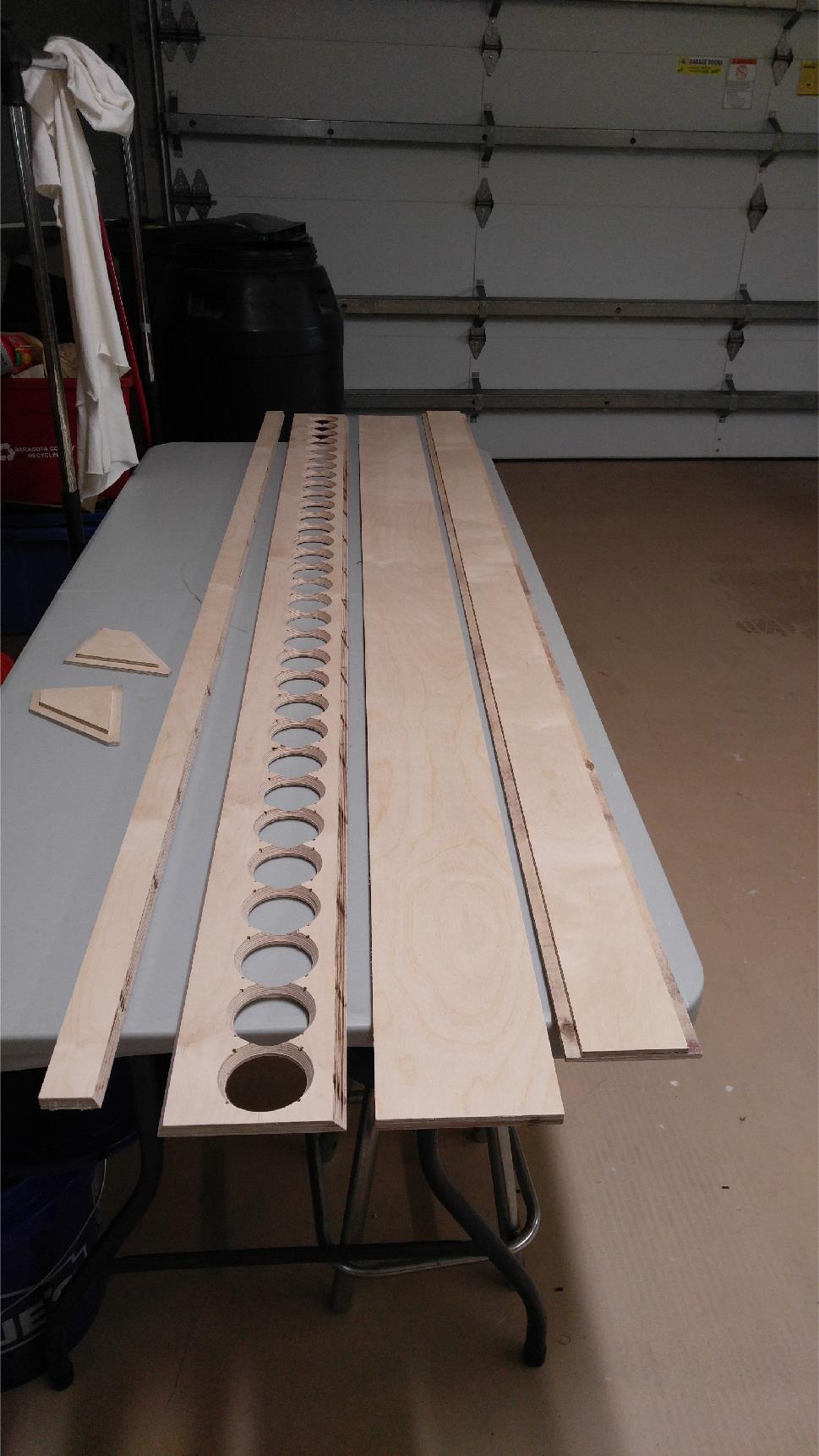
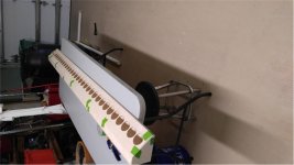
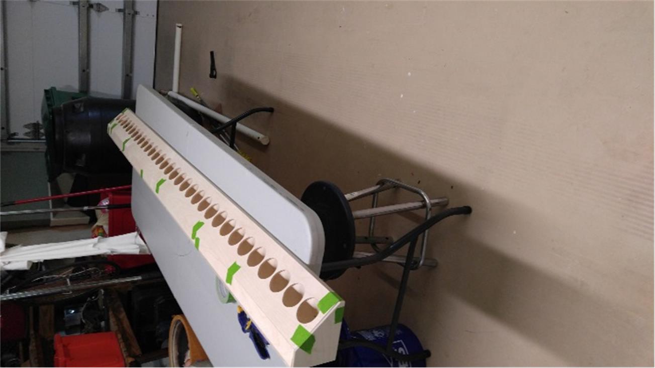
I'm finally ready to build the 2nd array. Here are the pieces all lined and ready to go. This design is simplicity itself. Just 6 pieces CNC cut so everything fits perfectly. Most of the time and work will be in mounting and wiring the drivers.
Were I to do it again, I would use 15mm instead of 12 mm plywood as individually each piece seems flimsy. Rigidity is achieved when they are glued together but I do need to beef up the end plates as they aren't thick enough to hold hurricane nuts for attachment of a baseplate.
Were I to do it again, I would use 15mm instead of 12 mm plywood as individually each piece seems flimsy. Rigidity is achieved when they are glued together but I do need to beef up the end plates as they aren't thick enough to hold hurricane nuts for attachment of a baseplate.
Attachments

See - they really do fit but I see I have to be really careful to keep the beveled edges aligned as I glue it. Had I had the opportunity to revise drawings before the 2nd build, I would have cut plates to fit inside the end plates and used them as temporary braces at the 1/3 and 2/3 marks as I glued.

Attachments
Uhoh! Driver mounting pilot holes are too large. Thought the screws for the first array went in way too easy.
Wanted 1/16", got 1/8". I drew at 1/8" but created CNC tool path that specified 1/16" but this didn't transfer to the CNC shop which created their own tool paths.
Heading to Home Depot for some wood filler....
Wanted 1/16", got 1/8". I drew at 1/8" but created CNC tool path that specified 1/16" but this didn't transfer to the CNC shop which created their own tool paths.
Heading to Home Depot for some wood filler....
See - they really do fit but I see I have to be really careful to keep the beveled edges aligned as I glue it. Had I had the opportunity to revise drawings before the 2nd build, I would have cut plates to fit inside the end plates and used them as temporary braces at the 1/3 and 2/3 marks as I glued.
Hi Jack
Do you use the tape method for gluing miters? I figure so
I've found running an extra layer of tape lengthwise, as per following vid, really helped me tighten/align long miters.
YouTube
Tried the video method with the boards pushed tight together, taped them up, then couldn't fold them enough to close the joint. Its not as easy as he made it look.
These bevels were 22.5 degrees each for a 45 degree corner but I don't know why that would matter.
Now I've got them taped together in place at 45 degrees. The corner is tight. I can open them up, put the glue in, fold them back together and put strips of tape holding the joint closed instead of clamps. That should work......tomorrow
- Home
- Loudspeakers
- Full Range
- Full range line array for wall or corner placement