Yes, that is interesting. There have been several array threads in the last few years in which the drivers weren't in a straight line that Vituix gives us the means to delve into.
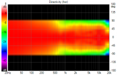
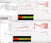
As far as the SEOS18 expanding array, I did nothing more than regenerate the 5FE120 directivity data with an 19" wide baffle and improved the directivity match at XO to this:

I would think that is good enough! In a corner, the waveguide doesn't quite keep the patterns off the wall; perhaps a 60H 40V would work better.
BTW Kimmosto just showed me how to simulate dipole, which is another interesting direction to branch into
https://www.diyaudio.com/forums/software-tools/307910-vituixcad-224.html#post6277330
dipole on the 5FE120s may keep it from widening below 500 Hz....
As far as the SEOS18 expanding array, I did nothing more than regenerate the 5FE120 directivity data with an 19" wide baffle and improved the directivity match at XO to this:
I would think that is good enough! In a corner, the waveguide doesn't quite keep the patterns off the wall; perhaps a 60H 40V would work better.
BTW Kimmosto just showed me how to simulate dipole, which is another interesting direction to branch into
https://www.diyaudio.com/forums/software-tools/307910-vituixcad-224.html#post6277330
dipole on the 5FE120s may keep it from widening below 500 Hz....
Attachments
Last edited:
.....BTW Kimmosto just showed me how to simulate dipole, which is another interesting direction to branch into.....
Thanks that was some of a controlled directivity pattern we get merge what Kimmosto modeled to yours
 ...
...Attachments
Last edited:
Cant afford the real Photoshop stuff but its their home user version called "Adobe Photoshop Elements" mine is a version 11 from year 2013 so will probably soon get me the latest Element version when i upgrade and leave this beatifull Win7 system for the Win10 road, look forward see that sim.
but its their home user version called "Adobe Photoshop Elements" mine is a version 11 from year 2013 so will probably soon get me the latest Element version when i upgrade and leave this beatifull Win7 system for the Win10 road, look forward see that sim.
Last edited:
Dipole woofer simulation
The dipole woofer simulation is very interesting!
To do this correctly, I created separate directivity files for the woofers on each side of the baffle center line. When I simulated this for sealed woofers, the dip at XO in the H DIR was larger than before. I shrugged my shoulders and moved on to the dipole sim.
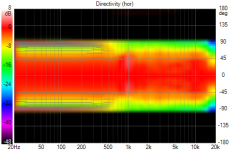
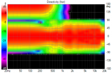
There I found I needed to reduce XO, all the way down to 800 Hz, the minimum recommended for BMS4550 and got these H Polars
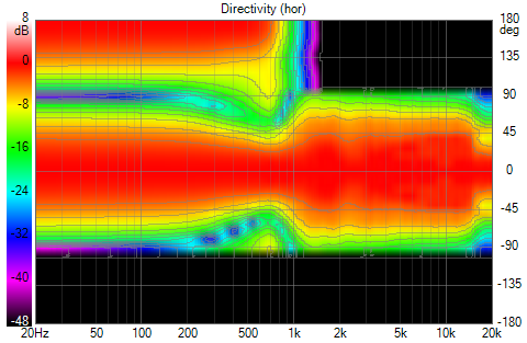
That yellow finger dipping down in the narrowing near XO goes away if I lower the XO still further, which I can do if I Synergize the SEOS18. Here is 500 Hz XO:
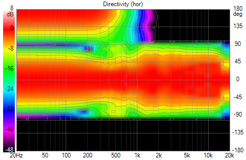
I don't know if it would be worth the trouble to Synergize the SEOS18. Note it loses horizontal pattern control around 750 Hz. The rest of data is at the 800 Hz XO.
The most striking thing about dipole is they help a lot neutralize the wall boundary interference. Here is room response with only wall reflections:
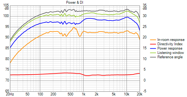
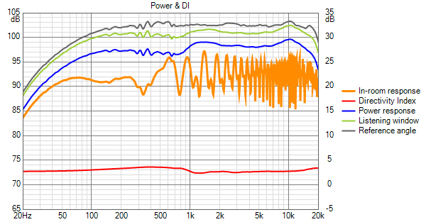
but floor and ceiling remain a problem for the waveguide portion of the response. Here is the same plot with wall, floor and ceiling reflections enabled:
The corner support has always been problematical for the standing height response. With dipole woofers that doesn't appear to be the case:
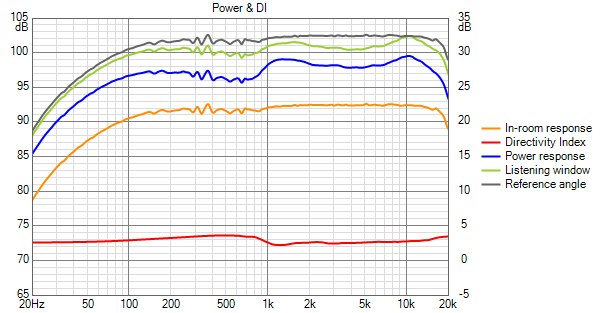
Yes, that room response is too good to be true and it is - floor and ceiling reflections aren't included. Floor and ceiling bounce do make it look more realistic:
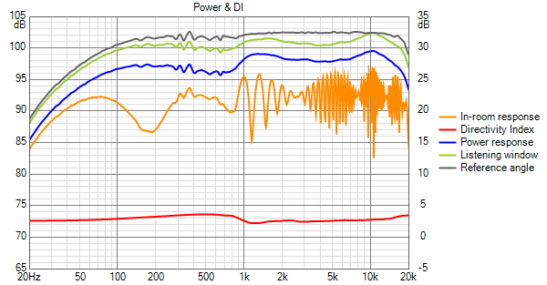
With this array, as with the more standard shaded arrays its hard to get a good response in the 100 Hz to 500 hz range. This is one of the better standing responses I've simulated and its better again because the dipoles have so much less trouble with wall reflections than the standard arrays. (Yes but walls are easier to treat than floor and ceiling)
To complete the story, here are the vertical polars:
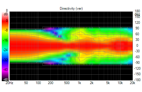
Don't put any faith in the low end of that graph - its a free space polar plot and doesn't take floor and ceiling into account. I think the room response can be trusted (as much as any sim) but not this polar plot.
The dipole woofer simulation is very interesting!
To do this correctly, I created separate directivity files for the woofers on each side of the baffle center line. When I simulated this for sealed woofers, the dip at XO in the H DIR was larger than before. I shrugged my shoulders and moved on to the dipole sim.
There I found I needed to reduce XO, all the way down to 800 Hz, the minimum recommended for BMS4550 and got these H Polars
That yellow finger dipping down in the narrowing near XO goes away if I lower the XO still further, which I can do if I Synergize the SEOS18. Here is 500 Hz XO:
I don't know if it would be worth the trouble to Synergize the SEOS18. Note it loses horizontal pattern control around 750 Hz. The rest of data is at the 800 Hz XO.
The most striking thing about dipole is they help a lot neutralize the wall boundary interference. Here is room response with only wall reflections:
but floor and ceiling remain a problem for the waveguide portion of the response. Here is the same plot with wall, floor and ceiling reflections enabled:
The corner support has always been problematical for the standing height response. With dipole woofers that doesn't appear to be the case:
Yes, that room response is too good to be true and it is - floor and ceiling reflections aren't included. Floor and ceiling bounce do make it look more realistic:
With this array, as with the more standard shaded arrays its hard to get a good response in the 100 Hz to 500 hz range. This is one of the better standing responses I've simulated and its better again because the dipoles have so much less trouble with wall reflections than the standard arrays. (Yes but walls are easier to treat than floor and ceiling)
To complete the story, here are the vertical polars:
Don't put any faith in the low end of that graph - its a free space polar plot and doesn't take floor and ceiling into account. I think the room response can be trusted (as much as any sim) but not this polar plot.
Attachments
-
 SEOS18 Dipole Woofers Hor Polars.png100.2 KB · Views: 326
 -
 Seos 18 Dipole Woofers Hpolars 500 Hz XO.png100.9 KB · Views: 314
 -
 Seos 18 Dipole Woofers Rm Resp Wall Refl Only.png30.7 KB · Views: 314
 -
 Seos 18 Dipole Woofers Rm Resp Wall floor ceiling Refl .png35.2 KB · Views: 309
 -
 Seos 18 Dipole Woofers Rm Resp Standing Wall Refl only .png29.7 KB · Views: 309
 -
 Seos 18 Dipole Woofers Rm Resp Standing All Refl.png35.4 KB · Views: 308
 -
 S18 dipole Vertical Polar Map.png86.3 KB · Views: 326
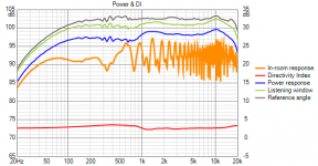
Thanks nice work/study could you share a zipped folder including "File/Export/Polar Frequency Responses" (create a empty destination folder before the export because VC nuke out 74x or so txt-files in one click), reason is the much talk about directivity plus room treatment preferences, you know for example B. Waslo added those BMRs to get reflections and Revel flagships wide spreaders is often prefered in test to JBL M2 flagship, Wesayso in a way constantly well its over very long time frame had small or tiny adjustments for tonality, so what i try to look for with your files is VC model of "In-room response" when we use the Room-tab compared to how it looks using a perfect omni, have attached my own homebrew below of a perfect omni 20Hz-20kHz BW2 stopbands. Would like to study those "In-room" visual pattern comparisons/predictions because if for example i ask a friend to play my acoustic guitar and sing situated in same spot as my speaker is then it sound absolut wonderfull and realistic and also it does open a door and listen from next room.
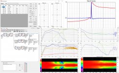
Below is ala yours response and using the perfect omni transducer but room number settings are not the same as in your model, disable VC Room-tab and its numbers orange curve is same as on-axis
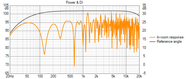
Below is ala yours response and using the perfect omni transducer but room number settings are not the same as in your model, disable VC Room-tab and its numbers orange curve is same as on-axis
Attachments
Thousand thanks, dirty fast graphs and their differences of In-Room response speaker at same spot/position into same room dimensions, on omni LW/ER/PR is hiding behind overlaid by on-axis and ERDI overlaid by DI, directivity looks good
Attachments
Last edited:
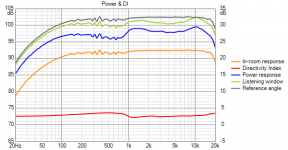
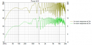
Thanks for the very interesting comparison of omni to this controlled directivity simulation in room. The orange grass is indeed deeper and thicker for the omni.
As noted earlier most of the grass in the SEOS18 response is due to floor and ceiling. I just looked and it reduces with shorter listening distances as more of the off axis sound hits beyond or bounces over the mic.

the level was reduced at 2m to separate the traces
As noted earlier most of the grass in the SEOS18 response is due to floor and ceiling. I just looked and it reduces with shorter listening distances as more of the off axis sound hits beyond or bounces over the mic.
the level was reduced at 2m to separate the traces
Attachments
Dipoles seem to be quite good at keeping sound off the walls. So too are waveguides. Earlier I posted a SEOS18 expanding array simulation. More recently polars were posted on Mabat's ATH thread for a 10"-12" square waveguide. I traced them to get directivity files to use in Vituix and came up with the following simulation. Its a W (MinWG) (CD in WG) (MinWG) W array.

The light gray line near the orange room response trace in the middle graph is the standing room response, the best I've seen here yet!
This simulation includes vertically stacked waveguides to extend the vertical pattern control of the waveguide to lower frequencies with the flanking waveguides overlapped with the central one playing from 500 Hz to 1 kHz. The vertically flanking WGs overlap the central one from 500 Hz to 1 Khz. Note in the polars how at 1 Khz, the pattern gradually widens horizontally, while more abruptly narrowing vertically.
Thus the central waveguide should use a 1.4" exit CD capable of playing down to 500 Hz in a home environment. All of the combing visible on the room response trace above 1 khz is with floor and ceiling. The 45 degree toed in WG does keep sound off the walls but not off the floor and ceiling. Listening distance does make a difference as to how much of this combing is seen. These graphs were taken at 2m and it floor combing increases at larger distances as one would expect due to geometry.
With a higher low pass cutoff for the flanking waveguides, the vertical pattern near WG XO narrows too much. At even higher frequencies, vertical sidelobes and combing would occur. The limited overlap gives line array like vertical response to the low end of the expanding array. The flanking waveguides would be driven by e.g. 6.25" drivers in bandpass chambers. We get good polars this way because of the matching waveguides and overlap.
15" woofers at top and bottom take over below 300 Hz.
Each driver or driver pair was first equalized to play flat over its range on a stand alone basis and at the same level as the others. Then a room response equalization was done on the full array. Thie room response equalization flattened the raised response in the overlap region, the raised bass due to corner support and a boundary dip in the 100 to 500 hz region.
Attachments
Last edited:
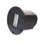
Could this be the central tweeter we need in an expanding array of TC9 drivers?
Viawave GRT-145

Not cheap by any means, but looking at the graphs it's quite impressive! It covers the bandwidth we'd need to hand it over smoothly to an array of TC9 drivers. A pair costs as much as the needed TC9 drivers for two arrays. But if it lifts up the total performance to otherwise unreachable levels.
I haven't played with sims yet, I just stumbled over the Troels page and it caught my eye between a bunch of super tweeters. This one stood out, not by a small margin. It seems like it could work both vertically and horizontally.
Viawave GRT-145
Not cheap by any means, but looking at the graphs it's quite impressive! It covers the bandwidth we'd need to hand it over smoothly to an array of TC9 drivers. A pair costs as much as the needed TC9 drivers for two arrays. But if it lifts up the total performance to otherwise unreachable levels
.I haven't played with sims yet, I just stumbled over the Troels page and it caught my eye between a bunch of super tweeters. This one stood out, not by a small margin. It seems like it could work both vertically and horizontally.
Attachments
I haven't played with sims yet, I just stumbled over the Troels page and it caught my eye between a bunch of super tweeters. This one stood out, not by a small margin.
Attachments
Could this be the central tweeter we need in an expanding array of TC9 drivers?
Viawave GRT-145
Not cheap by any means, but looking at the graphs it's quite impressive! It covers the bandwidth we'd need to hand it over smoothly to an array of TC9 drivers. A pair costs as much as the needed TC9 drivers for two arrays. But if it lifts up the total performance to otherwise unreachable levels
I haven't played with sims yet, I just stumbled over the Troels page and it caught my eye between a bunch of super tweeters. This one stood out, not by a small margin. It seems like it could work both vertically and horizontally.
I read on another forum (audioscience review) that Joachim Gerhard uses the Viawave SRT-7 in a range of his hi-end loudspeakers. Joachim was founder of Audio Physic and has 50+ years of experience designing hi-end speakers.
Joachim claims in some applications this is the best sounding tweeter and lowest distortion tweeter he came across (as long as crossover is not too low)


It was nice to see Ronald's thread come alive again for the New Year and its nice to have some activity here! Belated Happy New Year to all.
That appears to be a truly remarkable tweeter. Its only downside being the need for a high crossover. As I review my simulation results, that may disqualify it for use in the kind of arrays I had been looking into here where I got the best results with a waveguided 1.4" CD that played down to 500 Hz in a @mabat waveguide aided by dipole woofers.
That is not to say that this tweeter couldn't be made to work well in a larger room or one with fewer treatment constraints. Whether it would be worth the effort would be more about the room and the age of the listener's ears. I was looking for a treble response that was smooth and wide but not so wide as to hit the walls when placed in a corner. I didn't much care what happened above 16 kHz or so.
The hardest part of all this was getting a wide, seated through standing, vertical response. I think that is even more difficult with crossovers included in the response. If we only care about the seated response, its a much easier problem and a larger solution space. Recall that my initial attempt at a frequency shaded array had an almost laser-like vertical response but was also exceptionally smooth on the vertical axis.
The tweeter haraldo mentioned seems as excellent as the other one: Viawave SRT-7 ribbon tweeter | HiFiCompass
I do believe a tweeter like this could be a viable match to get rid of the vertical banding and creating a good seated/standing result with smooth results throughout.
As in creating a frequency dependent expanding array. Up to ~5 KHz the array performance is very clean already, no vertical side banding after the frequency dependent tweaks were done. Get this as a central tweeter and optimize it and one could keep that all the way up and keep the dynamics of the array and it's indifferent nature to floor/ceiling reflections...
I'm tempted to argue about how good the standing response would be if optimized for seated. Above crossover, you have the vertical response of the tweeter. I plotted an assumed vertical angle limit of 15 degrees based on the plots of the SRT7 and I see that at about 4m listening distance its feasible to have a good standing response:
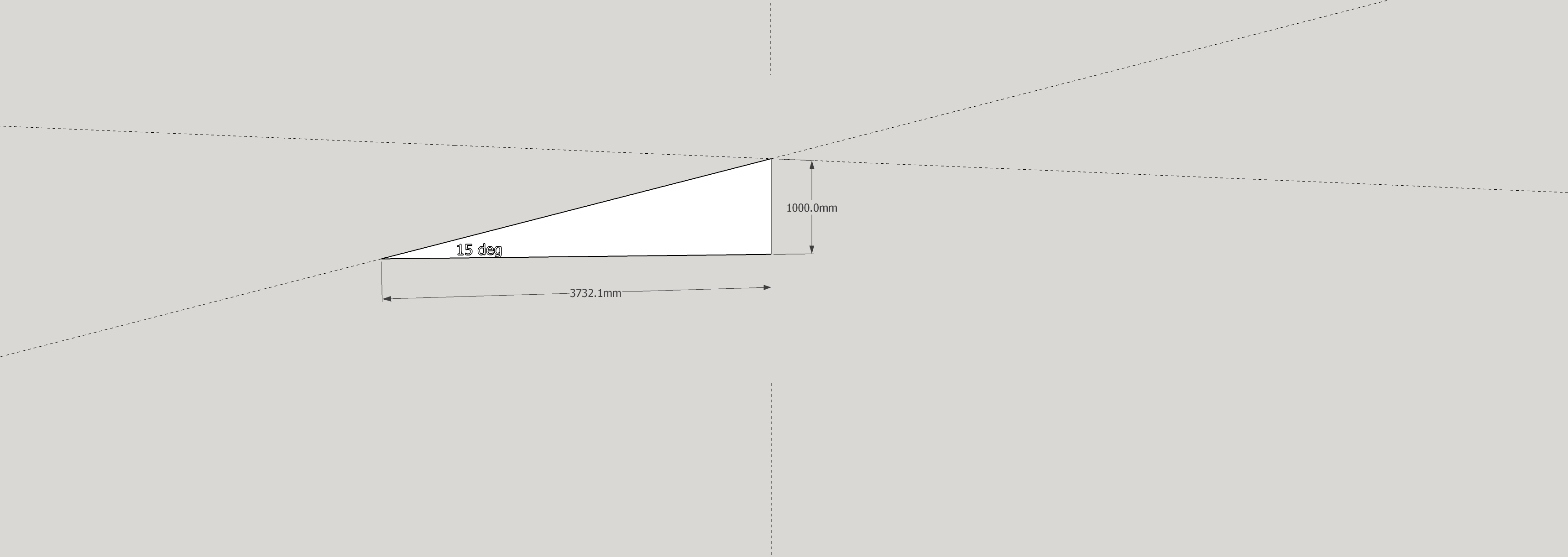
The response is there if you can get the crossover to stand up, so to speak
The response is there if you can get the crossover to stand up, so to speak
Attachments

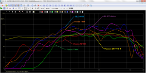
I modified my frequency shaded array sim with SB26 at center, replacing it with SRT7 and got these results that aren't too bad for just an hours effort. The vertical directivity gets a little too sharp around 1 khz.
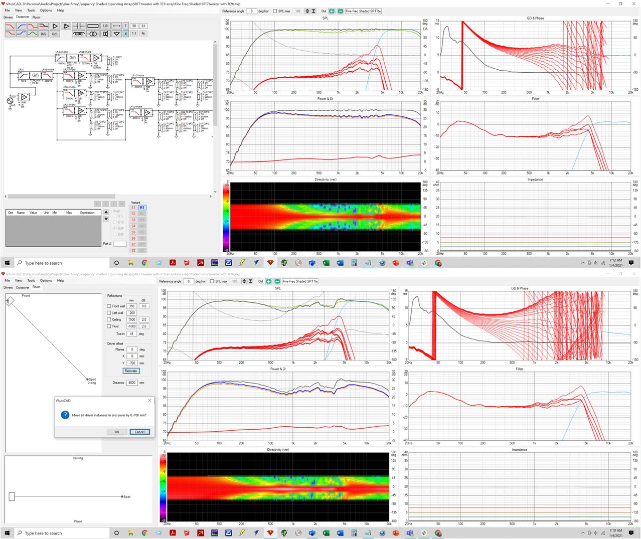
Yes, we'd like a passive filter version but this establishes feasibility and there is a weakness in that I only have 2 TC9s covering 3000 to 6000 Hz.
As crossover is lowered, the tweeter response widens, showing the value of a waveguided tweeter for that central position. And note that as simulated the tweeter is at array center, not ear height, which is something I haven't adjusted for.
Attachments
Thanks for running that sim. It does show what could happen with a tweeter like this at the center position. It also shows that there isn't sufficient vertical directivity to match the array, and if one would use the array to change that, the side bands would show up again due to the specific heart to heart dimensions, no free lunch.
The single center driver does cure the ragged response one would get with an arrayed top end, but when we include floor and ceiling reflections it would still tamper with the output around ~5 KHz where its pattern widens. So while it may be a little better with some care, it isn't a simple solution that miraculously fixes everything.
In other words: a rather expensive gamble. A vertically longer ribbon would likely be a better match, or one has to use an array of smaller drivers for the top end to move the side bands up in frequency. The fractal array being the best example I've seen so far.
- Home
- Loudspeakers
- Full Range
- Full range line array for wall or corner placement