Time to play, I bring some toys. The smallest variant of the Variera boxes and to that Aptitlig cutting boards. The idea is to use the latter as fronts. As they are on the narrow side I will add some "quarter rod" (that I do not know the english term for, please help me out.) To fill out the gaps on the sides. I also have some very slim about 2mm wide hardwood strips to use as braces.
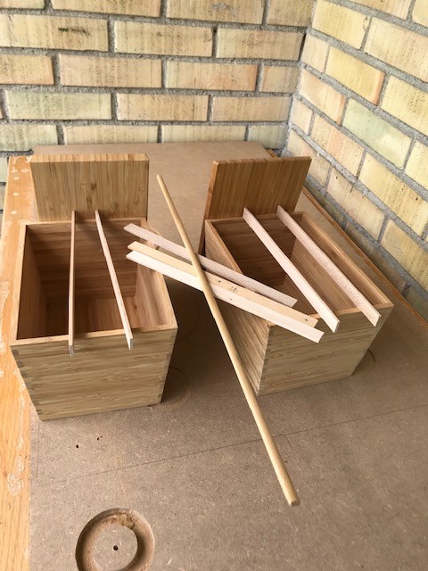
I bring some 3mm bitumen mats and some 10mm thick felt as well. I plan to line all the walls with felt. I will also wrap the bass reflex vent with that felt.

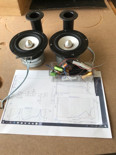
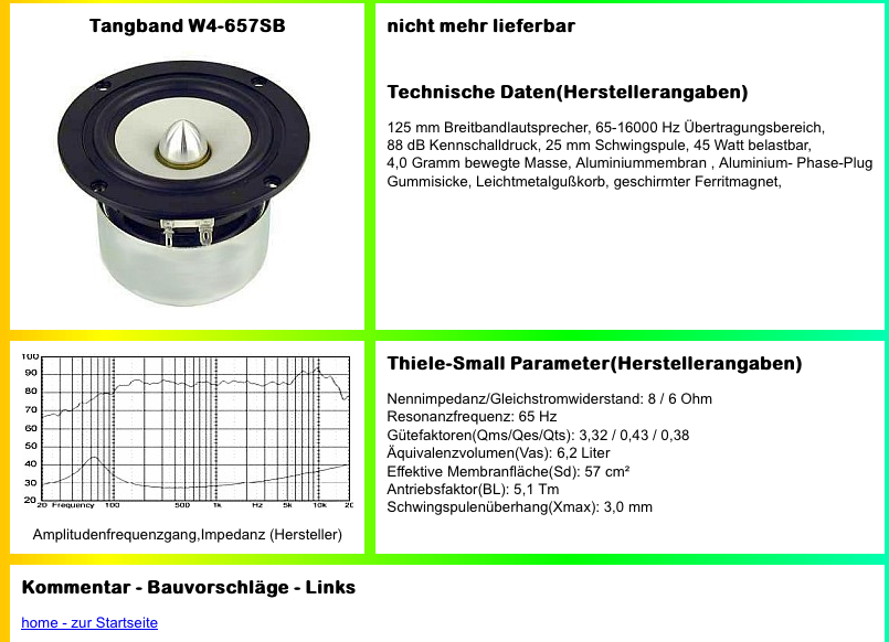
Last but no least Tangband We-756SB, supra cable, a filter with Zobel, baffle step and a trap to take down a resonance peak. This may have to be tweeked on the final baffle.
I bring some 3mm bitumen mats and some 10mm thick felt as well. I plan to line all the walls with felt. I will also wrap the bass reflex vent with that felt.
Last but no least Tangband We-756SB, supra cable, a filter with Zobel, baffle step and a trap to take down a resonance peak. This may have to be tweeked on the final baffle.
Looking good already. Nice components. Any more details on the TB driver?
I recently rebuilt mine and are sounding great. A bit bass light but that is expected. The imaging/ sounds stage is amazing. I use Faital 3fe22.
'quarter rod, is maybe what we might call 'quadrant'?!
I recently rebuilt mine and are sounding great. A bit bass light but that is expected. The imaging/ sounds stage is amazing. I use Faital 3fe22.
'quarter rod, is maybe what we might call 'quadrant'?!
Attachments
Last edited:
Bought about 15 years ago,
D 78 [mm] (that is effective diameter substracting the phase plug.
Re 6.073 [Ohms]
Fs 78.73 [Hz]
Zm 49.89 [Ohms]
BL 5.093 [N/A]
Qms 4.04
Qes 0.5599
Qts 0.4918
Vas 2.71 [liters]
L10k 0.3527 [mH]
n0 0.2252 [%]
dBSPL 85.63 [1W/1m]
Ms 4.835 [grams]
Cms 0.845 [mm/N]
D 78 [mm] (that is effective diameter substracting the phase plug.
Re 6.073 [Ohms]
Fs 78.73 [Hz]
Zm 49.89 [Ohms]
BL 5.093 [N/A]
Qms 4.04
Qes 0.5599
Qts 0.4918
Vas 2.71 [liters]
L10k 0.3527 [mH]
n0 0.2252 [%]
dBSPL 85.63 [1W/1m]
Ms 4.835 [grams]
Cms 0.845 [mm/N]
That's correct - 'quadrant moulding' is the full term.'quarter rod', is maybe what we might call 'quadrant'?!
If you’re talking about an end profile that resembles 1/4 of a circle then that is what we call quarter round molding here in the States.
https://www.bing.com/th?id=OIP.DCzDcvpAoKg2z_5r38AuoQAAAA&w=201&h=201&c=7&o=5&dpr=2&pid=1.7
https://www.bing.com/th?id=OIP.DCzDcvpAoKg2z_5r38AuoQAAAA&w=201&h=201&c=7&o=5&dpr=2&pid=1.7
Quarter round moulding it is, I will see if pine or oak suits best with the bambu look
I will build the filter with switches so I can test
1. Peak filter
2. Baffle step
3. Baffle step + peak filter at the flick of two switches.
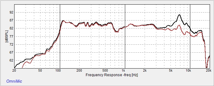
The frequency response was measured at less than optimal conditions so I am sure that the filter has to be tweed to measure OK and more importantly to sound good.
I will build the filter with switches so I can test
1. Peak filter
2. Baffle step
3. Baffle step + peak filter at the flick of two switches.
The frequency response was measured at less than optimal conditions so I am sure that the filter has to be tweed to measure OK and more importantly to sound good.
Drilled holes for Speakon connectors and some banan connectors as well. I used a 25mm wood drill and I got some splinters on the inside ugly...
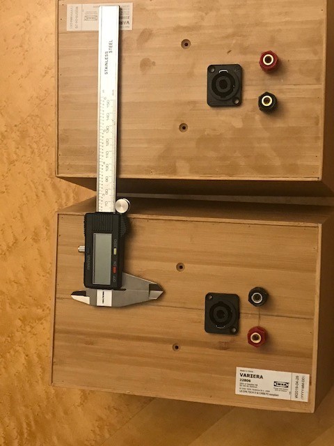
Hardwood braces 3mm thick and 16mm high. I think I add some 3mm bitumen between the braces. I have yet to decide how to brace the other five sides of the box. I use "no more nail" glue and the braces cover the predrilled screw holes.

Hardwood braces 3mm thick and 16mm high. I think I add some 3mm bitumen between the braces. I have yet to decide how to brace the other five sides of the box. I use "no more nail" glue and the braces cover the predrilled screw holes.
Last edited:
Back in the days many horns in Germany and Sweden was made using light and soft "softboard". They are supposes to store less energy than more dense boards. In the 80s we had the Celestion SL-600 with its hexcore aluminium skin walls with the same aim.
My aim is to get the box stiff to drive up the resonance frequency and then tame it with bitumen and felt.
My aim is to get the box stiff to drive up the resonance frequency and then tame it with bitumen and felt.
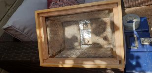
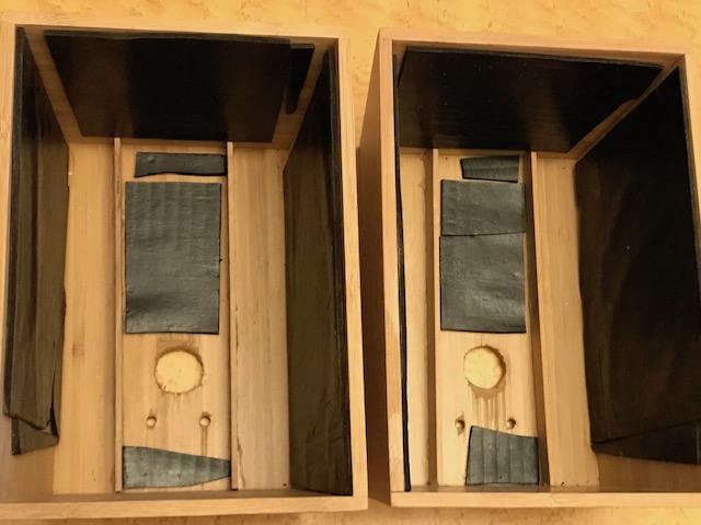
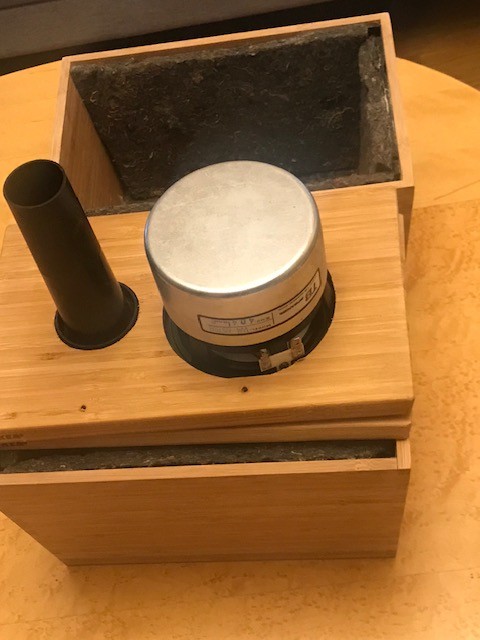
Bitumen in place on sides top and part of the backside.
Added 10 mm felt glued in place with PL-200 glue (as I had some leftovers)
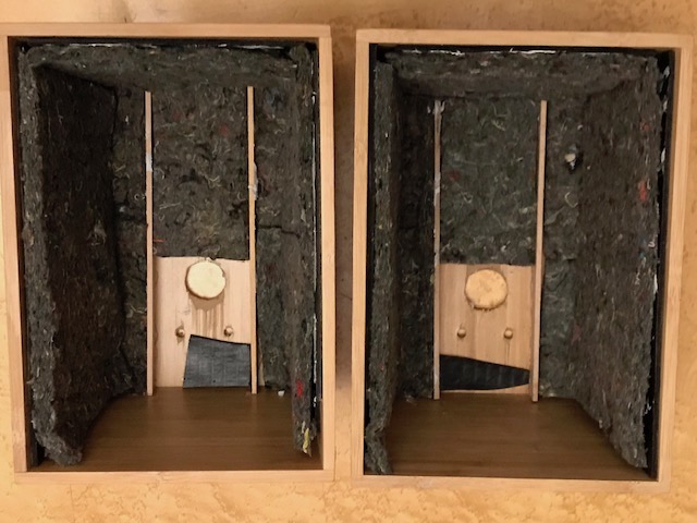
Next up is to mount the terminals, wire them and prepare for final placement of filter components. While trying the filter I will have it as one external one cobbled together.
Then it is time for cutting holes in the baffle and think about braces and damping.
Added 10 mm felt glued in place with PL-200 glue (as I had some leftovers)
Next up is to mount the terminals, wire them and prepare for final placement of filter components. While trying the filter I will have it as one external one cobbled together.
Then it is time for cutting holes in the baffle and think about braces and damping.
Very nice so far! Do you use the right-angled male Speakon connector? I'm contemplating using Speakon on a similarly sized speaker which will be a wedding present but I'm a bit worried about the aesthetics. The benefit is it's foolproof as they are not very technology-minded and they cannot short the amp with Speakon!
I have covered the predrilled holes with the braces.
I will use straigt Speakon connectors as I allready have some, if I run into a placement really close to a back wall I will change to angled ones.
The plan is to have the filter components at the bottom of the box, hence no felt on that surface. This surface will be partially "hidden" below the bass reflex tube that will be covered in a layer of felt.
Why do you tell us?The plan is to have the filter components at the bottom of the box, hence no felt on that surface. This surface will be partially "hidden" below the bass reflex tube that will be covered in a layer of felt.

Are there any other ways?
I have seen loudspeakers with the crossover embedded in wool or covered by foam. In the latter case with burn marks in the foam. If covered by insulation even minute power dissapation heat up the components in the filter. By having unrestricted airflow around thef filter I try to reduce this effect.
The official data. ( I bought them back in 2002!).
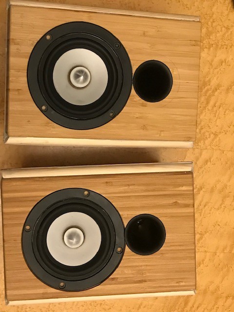
The driver is recessed 4 mm. When I bought the boards I did not notice that the colour of the two is quite different.
The driver is slightly further from the top than the sides and the vent is as close as I could get it. I did not use the tubes I showed before.

The box is quite filled with vent and the driver. I will have the driver pressfitted in the beginning and see if I need to shorten the pipe.
The driver is recessed 4 mm. When I bought the boards I did not notice that the colour of the two is quite different.
The driver is slightly further from the top than the sides and the vent is as close as I could get it. I did not use the tubes I showed before.
The box is quite filled with vent and the driver. I will have the driver pressfitted in the beginning and see if I need to shorten the pipe.
The boxes are finaly assembled. I used 9mm fir quarter mouldings and PL-200 setting glue as I had it at hand.
The compound angels were more difficult than expected, I also learned that pencil markings on wood is difficult to get rid of. So the final appearance is not up to what I had envision. But what the heck, it is a budget project, and fun

Next up:
1. Mount the drivers and measure frequency response and listen to them as well.
2. Find out if I need to change the bass reflex tuning, when that is done wrap the pipe in felt and glue the port in place instead of pressfit.
3. Then it is time for baffle step and all that filter thing.
The compound angels were more difficult than expected, I also learned that pencil markings on wood is difficult to get rid of. So the final appearance is not up to what I had envision. But what the heck, it is a budget project, and fun
Next up:
1. Mount the drivers and measure frequency response and listen to them as well.
2. Find out if I need to change the bass reflex tuning, when that is done wrap the pipe in felt and glue the port in place instead of pressfit.
3. Then it is time for baffle step and all that filter thing.
Last edited:
- Status
- This old topic is closed. If you want to reopen this topic, contact a moderator using the "Report Post" button.
- Home
- Loudspeakers
- Full Range
- Ikea Variera speakers