Dave, Scott : what's the rational behind using something like the 208Ez with high Zout amps in this context ? I have read Nelson's article several times over the years, but he's really looking mainly at the advantages for OB use in that assessment, and the upper frequency behaviour. Surely high Zout is just going to raise Qes a lot and hence Qts ? That must ( and is clear from sims on Hornresp ) alter both the amplitude and phase response of the driver on this horn, upsetting the clever acoustic balance ?
All I can remember Ron saying in this context is that you might try an ohm or two in series to tweak the response slightly.
All I can remember Ron saying in this context is that you might try an ohm or two in series to tweak the response slightly.
... between 20 and 50ohm output impedance...[/URL]
That would put the amp solidly in the current amp category. It might be a bit much. These are typically used and very good with SE tube amps which typically have an output impedance of 1-4 ohms, so still officially on the voltage amp side of zero but not by much.
The angles can be cut on a good table saw, perhaps a tenon jig would be handy). Out A126 build was done that way. Angles just as critical.
dave
For E / En / FFxx5K (old model) and ESigma series models, Fostex generally designed on the assumption that the drivers will be used on the end of an average SET or equivalent amplifier with an output impedance lurking in the 2.5ohm - 4ohm category, which was fairly typical for the classic US circuits & others. That's one of the reasons many of the drivers are so heavily over-damped as-is under voltage source conditions. Thus most enclosures either factor that and the effects upon the mass-corner frequency & effective Q into the load from the outset of the design, or need to. Dallas II, as I recall, assumed a degree of this sufficient to drop nominal Fhm with the design unit (defunct FE206E) down toward the uppermost point you could run a horn of this length without excessive GD and maintaining a reasonable response balance.
Last edited:
Yup. Not many as high as that, but they weren't unknown. You will note I make no statement advocating or detracting, nor that they were necessarily any more than very simple circuits repurposed; merely noting the fact of it, and that many of the Fostex units were designed assuming something across that broad region (confirmed to me by the chap who engineered many of them during his time there).
For e.g., assuming the defunct FE206E, Fhm with a voltage source is 433.33Hz. 2.5ohms drops that to 315.25Hz [nearly]. 4ohms to 271Hz [nearly]. Assuming a fairly typical bass horn path length of ~7ft the latter is preferable from the POV of the horn's upper corner frequency and minimising GD, with 2ohms - 2.5ohms being about the limit in an ideal world with that assumpion. This is assuming a flat targeted response and a moderately low tuning though; if you're OK with a bit less extension, the reduced path length will allow a slightly higher acoustic XO before GD becomes problematic. And depending on the design you may in any event only have a modest depression in the region between driver Fh and the horn's practical upper corner -sufficiently so not to be a big deal in practice.
For e.g., assuming the defunct FE206E, Fhm with a voltage source is 433.33Hz. 2.5ohms drops that to 315.25Hz [nearly]. 4ohms to 271Hz [nearly]. Assuming a fairly typical bass horn path length of ~7ft the latter is preferable from the POV of the horn's upper corner frequency and minimising GD, with 2ohms - 2.5ohms being about the limit in an ideal world with that assumpion. This is assuming a flat targeted response and a moderately low tuning though; if you're OK with a bit less extension, the reduced path length will allow a slightly higher acoustic XO before GD becomes problematic. And depending on the design you may in any event only have a modest depression in the region between driver Fh and the horn's practical upper corner -sufficiently so not to be a big deal in practice.
Last edited:
Thanks all for the contributions, much appreciated.
Looking through the Pass info available with low damping factors / high output impedances :
The ideal would be a SIT2 hover this seems to have parts that are unobtanium (DF=2)
Next may be the F3 (DF=8) but can't find the boards for them
Same going the other way with the F2J (DF=0.5)
So, it looks like the simplest to build and reasonable DF will probably be the ACA Monoblocks running at 24v / 15w. These have a damping factor of 10 (0.8ohm output resistance). Or, as I will be running the Fe208ez and the FT96h super tweeter would it be best to biamp using an 8W ACA for each driver pair ?
So, looking at the Dallas, if I make the sides rectangular and then add an additional rear piece then I may be able to fit the ACA board and heatsink onto the rear, like a plate amp or possibly using the original sloping rear fitting it into the lower cavity corner, either would make a very neat setup.
Thoughts ?
Last edited:
The lower cavity formed by the strike-plate ideally needs either mass-loading or with some kind of fill to avoid the potential for unwanted resonance, so I would avoid that. If you want to mount it on the back, that would work better in terms of the speaker's mechanics. However, being class A the ACA should have some space around it for proper heat dissipation, so I wouldn't personally try to physically mount it on or in a loudspeaker enclosure. It doesn't take up much space, and isn't unattractive, so I'd keep it separate if at all possible.
ACA or pair thereof. Nice bamboo / granite / marble / tempered glass / aluminium / whatever chopping board and some pretty spikes if you feel like it & you've suddenly got yourself your 'high-end anti-resonant amplifier support'. If you want to be really fancy, laminate a couple of materials together 'to alter the impedance match and enhance energy dissipation'.
And now I'm off to wash my mouth out with my anti-twaddle rinse.")
ACA or pair thereof. Nice bamboo / granite / marble / tempered glass / aluminium / whatever chopping board and some pretty spikes if you feel like it & you've suddenly got yourself your 'high-end anti-resonant amplifier support'. If you want to be really fancy, laminate a couple of materials together 'to alter the impedance match and enhance energy dissipation'.
And now I'm off to wash my mouth out with my anti-twaddle rinse.
Well the throat chamber has the bulk of the effect in forming the upper knee (?), although the driver mass corner will play a part.For e.g., assuming the defunct FE206E, Fhm with a voltage source is 433.33Hz. 2.5ohms drops that to 315.25Hz [nearly]. 4ohms to 271Hz [nearly]. Assuming a fairly typical bass horn path length of ~7ft the latter is preferable from the POV of the horn's upper corner frequency and minimising GD, with 2ohms - 2.5ohms being about the limit in an ideal world with that assumpion. This is assuming a flat targeted response and a moderately low tuning though; if you're OK with a bit less extension, the reduced path length will allow a slightly higher acoustic XO before GD becomes problematic. And depending on the design you may in any event only have a modest depression in the region between driver Fh and the horn's practical upper corner -sufficiently so not to be a big deal in practice.
I think it's a questionable logical step to think that Ron made the same assumptions as the Fostex engineers did, about how their drivers would be used. Given that he didn't like valve amps, or use them himself ( see some of his postings ) it's safe to assume he was assuming low driving Z as the starting point.
I suspect you'd have to put a bigger baffle on the front to do what you're suggesting.
Also remember that pulling the horn contribution down further with series resistance will also affect the phase rotation where the front and rear outputs combine - which would have been carefully considered in Ron's computer model.
I suppose the aim of your suggestion would be to tame some midrange/HF effects on the 206 ?
October 2006 -
Quote: (Martin King ) -
"I am not so sure. Remember that most of the hit or miss full range BLH designs are paired with low power tube amps. The output impedance of the tube amps is all over the map. So the effective Qts of the driver probably has a significant tolerance leading to a large variability in the required CC volume. The only way I see of tightening the tolerance on the CC is to design for SS amps. But that would be a non-purist approach and looked down on by the enlightened "
Ron Clarke -
"I try to design for the " middle of the road" approach. True its not optimum, but its the only approach i can take for the masses. Most don't understand that the amp is part of the system, or the room volume or shape or even the source. To truly design for a given set of conditions would require several designs that i truly don't have time in my life for.( just discovered fly fishing for stream trout in NC with my lady, a hell of a lot more enjoyable than designing automated inspection systems for industry)"
The driver's lower corner frequency under a given set of drive conditions (and with support from a given baffle size) is a different thing to the upper corner frequency of the horn. They are linked in design terms though; the ideal is to ensure that the former is lower, or no higher than, the latter. Back loaded bass horns have a practical upper limit governed not only by the baseline FR but also by the audibility of group delay which is a question of the physical path length.
In the case of the FE206E, under voltage drive conditions it is massively over-damped (at least, per the factory specs., which were a mite optimistic) with a -3dB mass corner frequency up around 433Hz on a large baffle. Thus with a typical back loaded bass horn you either need some help from the amplifier / series R to lower this rolloff frequency to the practical upper frequency limit of the horn, or accept a hole in the response between the two points, or the potential for audible GD in this region. That's all I'm referring to, which are simply basic facts, not recommendations; amplifier output impedance was not a subject I mentioned until you asked, and at no point have I suggested a given value for Dallas II, merely noting that a small amount or the equivalent in terms of series R was included in the design assumptions, as it should be for any quality loudspeaker design. That, broadly speaking, is what quality 'middle of the road' design refers to, or at least that's what I refer to as such and AFAIK Ron meant too: accounting for what you can, without going to extremes. Speaking for myself, as you know, I use solid state amplifiers with a low output impedance myself; I appreciate quality valve amplifiers, but I don't have the space or money, and I need the day in, day out consistency that they aren't ideally suited to. Many people do though, so power to them, and providing the context is known, there are potential advantages under given conditions, the downside there being to ensure that the context is known.
More specifically, Ron tended to run his horns a little higher than some, using quite a well-defined upper corner frequency and acoustic low pass to reduce the impact as far as possible, while also building some latitude for a small amount of series R / higher amplifier output impedance in the circuit so there's a bit of flexibility. This works well, but with the objective hat on, it still entails some compromises: for e.g. the original Austins had a slight 'cuppy' sound, partly due to the physically small chamber and resulting immediate pressure effects on the driver, but also partly due to a slight mismatch between the driver rolloff on the baffle & the upper limit of the horn. Fairly easily fixed (and he did), but the optimal solution for drivers with a high mass corner frequency and a voltage source was / were the compound horn he was working on (still was, last time we emailed) before he stepped back from as much involvement with audio; in this case, the short midrange horn filling in the gap between the practical upper limit of the bass horn and the driver's mass corner rolloff on the design baffle. That's the favourite, since you can use a lower cutoff for the bass horn, more or less eliminating audible GD while maintaining a well-balanced response.
In the case of the FE206E, under voltage drive conditions it is massively over-damped (at least, per the factory specs., which were a mite optimistic) with a -3dB mass corner frequency up around 433Hz on a large baffle. Thus with a typical back loaded bass horn you either need some help from the amplifier / series R to lower this rolloff frequency to the practical upper frequency limit of the horn, or accept a hole in the response between the two points, or the potential for audible GD in this region. That's all I'm referring to, which are simply basic facts, not recommendations; amplifier output impedance was not a subject I mentioned until you asked, and at no point have I suggested a given value for Dallas II, merely noting that a small amount or the equivalent in terms of series R was included in the design assumptions, as it should be for any quality loudspeaker design. That, broadly speaking, is what quality 'middle of the road' design refers to, or at least that's what I refer to as such and AFAIK Ron meant too: accounting for what you can, without going to extremes. Speaking for myself, as you know, I use solid state amplifiers with a low output impedance myself; I appreciate quality valve amplifiers, but I don't have the space or money, and I need the day in, day out consistency that they aren't ideally suited to. Many people do though, so power to them, and providing the context is known, there are potential advantages under given conditions, the downside there being to ensure that the context is known.
More specifically, Ron tended to run his horns a little higher than some, using quite a well-defined upper corner frequency and acoustic low pass to reduce the impact as far as possible, while also building some latitude for a small amount of series R / higher amplifier output impedance in the circuit so there's a bit of flexibility. This works well, but with the objective hat on, it still entails some compromises: for e.g. the original Austins had a slight 'cuppy' sound, partly due to the physically small chamber and resulting immediate pressure effects on the driver, but also partly due to a slight mismatch between the driver rolloff on the baffle & the upper limit of the horn. Fairly easily fixed (and he did), but the optimal solution for drivers with a high mass corner frequency and a voltage source was / were the compound horn
Last edited:
..amplifier output impedance was not a subject I mentioned until you asked, and at no point have I suggested a given value for Dallas II, merely noting that a small amount or the equivalent in terms of series R was included in the design assumptions
No not you at first, but it was Dave suggesting that you use high output impedance that got me confused. Then ugg10 linked to Nelson Pass's article and I thought we were going down a route of current-sourced amps for this.
I see the 433Hz -3dB value you quote but it doesn't look that high on the FE206E/En datasheets for an IEC baffle so I suspect the Q might be a little higher - wouldn't be the first time with a Fostex driver !
Florin seems extremely happy with the Dallas's driven by what looks like an output impedance around 2 to 2.5R ( if it doesn't use feedback ) so all is well ;o)
https://cdn.shopify.com/s/files/1/1006/5046/files/ACA_Monoblock_Operation_RevA.pdf
Just spotted this which gives details of the various aca operating modes. Balanced Mono looks like it could be the best option but this may need a change in my source, a seconded best would be the unballanced mono but you don’t get the distortion cancelling benefit. But 1.6ohm output impedance is getting close to ideal particularly as it will see about 4ohms with the fe208 and Ft96h running in parallel.
Just spotted this which gives details of the various aca operating modes. Balanced Mono looks like it could be the best option but this may need a change in my source, a seconded best would be the unballanced mono but you don’t get the distortion cancelling benefit. But 1.6ohm output impedance is getting close to ideal particularly as it will see about 4ohms with the fe208 and Ft96h running in parallel.
Cool, thanks @IslandPink, much appreciated. I expect with the 1uF cap (or there abouts, comment on other threads seem to suggest a 0.68uF may be better but can experiment) and the Lpad, the tweeter will come in at around 8-10kHz where the FE208EZ starts to drop off.
Should have looked at the data sheets - FT96H is 8+ ohms and rising in this area and the FE208EZ looks like it is around 12 ohms and rising. So all looks go for an easier load than I originally thought.
Sooooo much to learn but looks like I am converging on a system design (rather than individual items) that may not work together.
- FE208EZ+FT96H Dallas II Horn (as standard)
- ACA Amp in Balance XLR Input Mono Mode (2 off) giving output impedance of 1.6 ohm and 15W into 8 Ohm load.
For ref
https://www.fostexinternational.com/docs/speaker_components/pdf/fe208ez.pdf
https://www.fostexinternational.com/docs/speaker_components/pdf/FT96H.pdf
https://www.fostexinternational.com/docs/speaker_components/pdf/att.pdf
...anti-resonant amplifier support’...
The ACAs — at least the full diyAudio kit — could use a bit of damping sheet on the top plate. I really like these running in mono or as stereo amps.
I would not bi-amp, the tweeter is covering 2 octaves at best, and a simple cap XO has proven to be a decent solution.
dave
@planet10, thanks, looks like the balanced mono version at 15w with 24v supplies seems to be the best option, I have a studio passive preamp so can feed it balanced from that I think (M-Patch Pro v2) otherwise I could upgrade my streaming source to a Cambridge audio CXN or 851n.
Your comment about the lid, do you mean that the box top is just a bit thin or is there a sound issue with it. I am planning on making my own box so not a big issue, just interested to know.
Your comment about the lid, do you mean that the box top is just a bit thin or is there a sound issue with it. I am planning on making my own box so not a big issue, just interested to know.
As I recall, the top and bottom are the same gauge aluminum, but of course with the rubber feet supplied, even the relatively light weight of the chassis was enough to dampen resonance of the bottom. It only took a very small square of Dynamat type material on the underside of top cover to reduce its resonance to a dull "thonk"
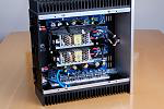
I am looking at putting the 4 boards (stereo monoblocks) in one box including the power supply’s so only one iec plug on the rear. I have found some nice 300x125x50 heatsink which have more area than two of the 200x80x40 diyaudiostore ones (37.5k sq.mm vs 32k sq.mm). I will add a 5mm aluminium base and rear and then thinking of some nice 5mm or 6mm coloured acrylic panels for the front and top, top may be clear or semi opaic if I can get my wiring neat enough !
Probably getting off track in this thread but has anyone unboxed the power supplies and mounted them inside the aca box. I have seem them inside but still intact which does not look nice.
Many thanks for all of the replies, much appreciated.
Probably getting off track in this thread but has anyone unboxed the power supplies and mounted them inside the aca box. I have seem them inside but still intact which does not look nice.
Many thanks for all of the replies, much appreciated.
Might be less work to source a single appropriate sized SMPS by some one like Connex, Meanwell, etc., something that Tom at Neurochrome has found works quite well as an affordable option to linear PSU. I know that at least two of the three different models of his amps that I’ve heard over the past few years - including the 220W Mod 686 were so powered.

Attachments
Last edited:
- Status
- This old topic is closed. If you want to reopen this topic, contact a moderator using the "Report Post" button.
- Home
- Loudspeakers
- Full Range
- Dallas II modification