Hi all!
So after the great success (and continuing tweaking success) of my low group delay vented mains with the Alpair 7MS (MLTL Floorstanders for Alpair 7MS) I am turning my attention to re-purposing my A6.2M drivers as surrounds.
http://kjfaudio.com/wp-content/uploads/2016/10/Alp6M_Gen.2-june2011.pdf
What I learned from the above was that size and GD need not get in the way if the box is designed right if only a limited BW is needed.
Aims:
- Small as possible.
- Slim as possible to be positioned on a shelf/chest of drawers or wall mount.
- Cheap.
- Low GD as they will be crossing over to my dual subs/bass units somewhere between 90-100hz using an analogue Behringer CX2310 which has LR 24db slopes.
- The possibility to be used as mains with a subwoofer again somewhere down the line if needs be.
Blue is 3.3 litres with a vent at 63hz.
Green is 2.5 litres with a vent at 75hz.
Orange is 2 litres with a vent at 75hz.

As can be seen GD is at around 4-5ms at approx crossover point (90-100hz) - respectable, as I am led to understand.

If I had to pick from the FR graphs I would go for the green at 2.5 litres but, is there a way to get a better response from a 2 litre enclosure?
After reading about garym999's thread (Alpair 7/11 MS for surround sound?) to use the 7MS for a surround system I would have to pay attention to reflections from a close back wall being such a small and slim enclosure.
Can anyone give critique on my approach so far, please?
Any input is welcome!
Cheers, G.
So after the great success (and continuing tweaking success) of my low group delay vented mains with the Alpair 7MS (MLTL Floorstanders for Alpair 7MS) I am turning my attention to re-purposing my A6.2M drivers as surrounds.
http://kjfaudio.com/wp-content/uploads/2016/10/Alp6M_Gen.2-june2011.pdf
What I learned from the above was that size and GD need not get in the way if the box is designed right if only a limited BW is needed.
Aims:
- Small as possible.
- Slim as possible to be positioned on a shelf/chest of drawers or wall mount.
- Cheap.
- Low GD as they will be crossing over to my dual subs/bass units somewhere between 90-100hz using an analogue Behringer CX2310 which has LR 24db slopes.
- The possibility to be used as mains with a subwoofer again somewhere down the line if needs be.
Blue is 3.3 litres with a vent at 63hz.
Green is 2.5 litres with a vent at 75hz.
Orange is 2 litres with a vent at 75hz.
As can be seen GD is at around 4-5ms at approx crossover point (90-100hz) - respectable, as I am led to understand.
If I had to pick from the FR graphs I would go for the green at 2.5 litres but, is there a way to get a better response from a 2 litre enclosure?
After reading about garym999's thread (Alpair 7/11 MS for surround sound?) to use the 7MS for a surround system I would have to pay attention to reflections from a close back wall being such a small and slim enclosure.
Can anyone give critique on my approach so far, please?
Any input is welcome!
Cheers, G.
Last edited:
You might look into a small a short tapered TL with progressively dense stuffing. What you want to do is tune the TL in such a way that it rolls off as shallow as possible and that is what gets low GD (GD is slope of FR curve). The falloff of a stuffed and tapered TL is shallower (slower roll-off) than a regular bass reflex vented alignment. My guess is that you should be able to get it down to about 2.5ms to 3ms at 100Hz.
Here is PMC inspired TL using a Dayton DC130A predicted GD:
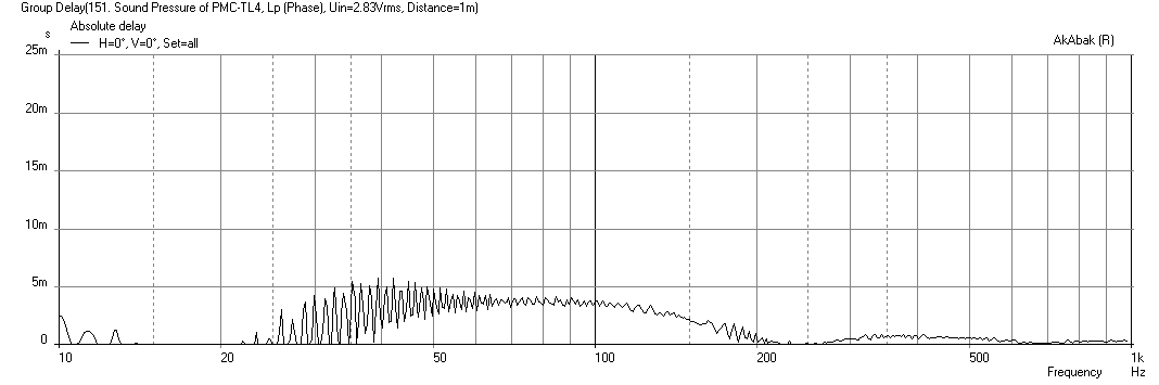
Low-Cost PMC-inspired TL Monitor with DC130A and DC28F
Here is PMC inspired TL using a Dayton DC130A predicted GD:
Low-Cost PMC-inspired TL Monitor with DC130A and DC28F
Last edited:
Thanks, xrk971.
This is something I definitely want to try in the future but sadly space prohibits it unless, I'm being naive and a TL could be sized down to around 2.5 litre box?
Would a GD time of 2.5ms be hugely different in function and integration over a 5-6ms GD in this application (limited passband of 90hz+).
Interesting thread and read, I've always lusted after PMC's after having a track mastered in a studio with large PMC mains. Well done on the work there!
If you are only looking to go to 70-90 Hz, I think a 4.3L (internal volume not including thickness of wood) can be done with a 4.5in wide x 9in tall x 6.5in deep, triple folded (4 paths up and down) 36in long TL with a 3:2:1:0.5 channel depth ratio.
Perhaps check out the Lance TL and see if that can work for you - it will fit a 3.5in driver nicely.
http://wodendesign.com/downloads/Woden-BabyLabs-081015.pdf
Perhaps check out the Lance TL and see if that can work for you - it will fit a 3.5in driver nicely.
http://wodendesign.com/downloads/Woden-BabyLabs-081015.pdf
So, after something thinking I've decided to go with the 2 litre box option and to crossover over somewhere between 100-110hz.
Size is a very important factor here as my fiance just walked in a caught me drawing this design and exclaimed "WHAT?!? More speakers?!?"
GD is just under 4ms.
I have used the golden ratio for the enclosure which is very slim. Presumably I will have to damp the rear panel a little thicker than I would normally have to as the enclosure is only just double the depth of the driver.
The vent is position in the side of the enclosure. I realise this means it will be close to the wall which it will be mounted on or positioned closely to but I can't see a simple or better solution to this, really.
Attached are two images I knocked up with this plan so far. After drawing them I decided to go with 18mm baffle and rear panel and 15mm sides. This should keep stiffness.


As always, thoughts are always appreciated!
Size is a very important factor here as my fiance just walked in a caught me drawing this design and exclaimed "WHAT?!? More speakers?!?"
GD is just under 4ms.
I have used the golden ratio for the enclosure which is very slim. Presumably I will have to damp the rear panel a little thicker than I would normally have to as the enclosure is only just double the depth of the driver.
The vent is position in the side of the enclosure. I realise this means it will be close to the wall which it will be mounted on or positioned closely to but I can't see a simple or better solution to this, really.
Attached are two images I knocked up with this plan so far. After drawing them I decided to go with 18mm baffle and rear panel and 15mm sides. This should keep stiffness.
As always, thoughts are always appreciated!
Graham - I’d built most of the models in Scott’s Baby Lab* series, and they work very well. For the A6.2, the Stinger (page 8 of cited planet, I think) would be the appropriate model, and while I think you’ve indicated in other threads your prefernce for MDF, a good quality plywood is worth considering. Whatever material you use, definitely pay attention to chamfering rear side of driver cutout.
*Mr Lindgren has a well establish track record of decent sounding enclosures for a wide range of driver makes and models - I’ve built dozens of them myself, and aside from drivers I’d just not cottoned to for whatever reason, have never been disappointed.
*Mr Lindgren has a well establish track record of decent sounding enclosures for a wide range of driver makes and models - I’ve built dozens of them myself, and aside from drivers I’d just not cottoned to for whatever reason, have never been disappointed.
Thanks, Chris. Yes, Scott makes excellent designs.
I really wanted to keep volume low as I am invading our front room space and my fiances pokerface can only be tested so far.
I really wanted to keep volume low as I am invading our front room space and my fiances pokerface can only be tested so far.
Graham - I’d built most of the models in Scott’s Baby Lab* series, and they work very well. For the A6.2, the Stinger (page 8 of cited planet, I think) would be the appropriate model, and while I think you’ve indicated in other threads your prefernce for MDF, a good quality plywood is worth considering. Whatever material you use, definitely pay attention to chamfering rear side of driver cutout.
*Mr Lindgren has a well establish track record of decent sounding enclosures for a wide range of driver makes and models - I’ve built dozens of them myself, and aside from drivers I’d just not cottoned to for whatever reason, have never been disappointed.
Well, I built and measured them and they have come out as expected which is great, even if it is a simple design and for a reason.

Aren't they cute in a short of stubby stout functional way. I'll chamfer, fill and paint next, obvs.
Attached is a measurement at 18cm. As always in my test spot I get a little null around 50hz so ignore that.

Would this be a good measurement to base BSC on? If so any thoughts on where to start? It clearly needs attentuation at 1k.
I have done some MiniDSP fiddling and found a set of EQs that make them very nice. Can this be made a passive EQ, obviously it would have to be less specific and slightly slightly more broad in its frequency ranges and localisation.

These settings make it flat from 110 to 10k which 5 db roll off of the highs above 15k.
Any thoughts on how to achieve this? I've yet to venture in to BSC and passive crossover EQ'ing. Is there something acoustic I can do?
As always, thoughts would be appreciated.
G.
Aren't they cute in a short of stubby stout functional way. I'll chamfer, fill and paint next, obvs.
Attached is a measurement at 18cm. As always in my test spot I get a little null around 50hz so ignore that.
Would this be a good measurement to base BSC on? If so any thoughts on where to start? It clearly needs attentuation at 1k.
I have done some MiniDSP fiddling and found a set of EQs that make them very nice. Can this be made a passive EQ, obviously it would have to be less specific and slightly slightly more broad in its frequency ranges and localisation.
These settings make it flat from 110 to 10k which 5 db roll off of the highs above 15k.
Any thoughts on how to achieve this? I've yet to venture in to BSC and passive crossover EQ'ing. Is there something acoustic I can do?
As always, thoughts would be appreciated.
G.
Last edited:
Morning all!
So, today I will do some BSC tests. I ordered and received the following in order to be able to do 1ohm adjustments on this 4ohm driver:
0.68mh ferrite core inductor
1ohm resistor
2.2ohm resistor
3.9ohm resistor
I ordered these particular resistors as in different combinations I can roughly achieve 1, 2, 3, 4, 5, 6 & 7ohm increments in adjustment.
Annoying, only yesterday did I discover the MJK BSC spreadsheet and paper, DANG. After reading this I now know that the inductor value will need to be changed as the resistor value changes in order to keep the same centre frequency.
My baffle width is only about 6 inches wide and gives quite a high (around 700hz) BSC point. Is this that crucial at this frequency point?
Also, the spreadsheet recommends a zoebel filter, is this essential and will it effect the value given on the MJK spreadsheet?
And also again, when measuring, should I have my mic at the listening position? I will be using my ears as well, of course.
http://www.quarter-wave.com/General/BSC_Calculator.xls
http://www.quarter-wave.com/General/BSC_Sizing.pdf
Looking forward to getting stuck in today!
Last edited:
Look at your minidsp settings, you start that broad notch at 200Hz.
To get somewhat close to that, you will need quite a beefy inductor.
Your 0.68mh will start taking off steam at around 2kHz, right where you naturally have a slope going down... You'll just exacerbate that fall, and have those mids way too strong with nothing low, and not much high.
Do yourself a favor and get a XO simulation software, like XSim, and learn what stuff does.
Use your own curves, and design something appropriate.
You are using textbook baffle stuff, but the drivers also a say in this... In this case, the high mids of the MA drivers.
Last edited:
Thanks for your input, Perceval. I have indeed already simmed this in X-Sim but perhaps I did not get it right. Perhaps I should have been more explicit in my previous post - at the moment I am just trying traditional BSC. It is my first time with passive audio components so I don't expect to get anything right first time, on I plod!
So, after realising that (as Perceval mentions) a 0.68mh inductor is too low a value my conclusion is move up to a 1mh and perhaps a 1.5mh inductor. I have simmed these but the response doesn't seem to respond as I would have expected.
I'm only using iron-core inductors so are quite cheap at about £3 a go. Is it worth me trying these or is 1.5mh just way to high? Suck it and see, I suppose!
A 1.5mH and 10 Ohms flattens the mid range, but there's a 7dB drop at 1.5kHz. Not great.
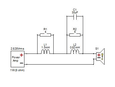
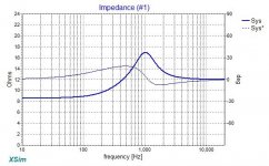
the most minimal impact on impedance I could get is with a 0.82mH inductor, a 30uF cap and a 6 Ohms resistor notch.

There's still that cone break up at 12kHz... and if you don't aim the speakers directly at the head of the listener, it should have an ok drop in HF.
Feel free to play with this to see if you can come up with something better...
the most minimal impact on impedance I could get is with a 0.82mH inductor, a 30uF cap and a 6 Ohms resistor notch.
There's still that cone break up at 12kHz... and if you don't aim the speakers directly at the head of the listener, it should have an ok drop in HF.
Feel free to play with this to see if you can come up with something better...
Attachments
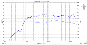
Thanks, P. I re-measured a box from my listening position and have applied the your suggestion and BSC.
I'm not sure how to have multiple graphs overlaying in X-Sim so please excuse multiple images.
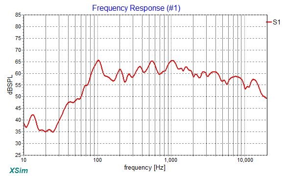
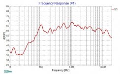
Frequency response from listening position with no sub, crossover or EQ(my room gives a dip around 200hz, please ignore this area):

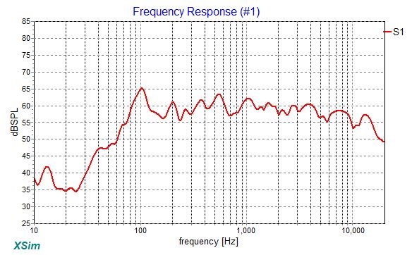
The above with BSC (1.5mh & 4ohms):
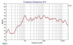
The above with BSC and your proposed notch filter (0.82mh, 6ohms, 30uf):

As I have mentioned above I am a novice when it comes to passive components but want to learn. Even to me the above circuit feels excessive but I can't say why.
The graph with notch and BSC does look neat, though!
I'm not sure how to have multiple graphs overlaying in X-Sim so please excuse multiple images.
Frequency response from listening position with no sub, crossover or EQ(my room gives a dip around 200hz, please ignore this area):
The above with BSC (1.5mh & 4ohms):
The above with BSC and your proposed notch filter (0.82mh, 6ohms, 30uf):
As I have mentioned above I am a novice when it comes to passive components but want to learn. Even to me the above circuit feels excessive but I can't say why.
The graph with notch and BSC does look neat, though!
Attachments

Last edited:
It's not excessive if it's needed to sound good.
But you could do away with the BSC to save some cost.
Like I said, just angle the drivers away from the listeners head by 15 degrees and you will have a natural BSC.
Also, for your setup to be perfect, you would need to get the impedance curve of your driver in your box. That can be found using software like DATS, or even with REW, just follow the procedure.
Last edited:
- Status
- This old topic is closed. If you want to reopen this topic, contact a moderator using the "Report Post" button.
- Home
- Loudspeakers
- Full Range
- Alpair 6.2M Low Group Delay Vented Surrounds