Those heat sinks are way too tiny! They're designed for use in fan-cooled systems. You need to provide an airflow of 600 LFM to get to the published thermal resistance of 0.6 K/W. Judging by the curve in the data sheet, you might be able to get away with 400 LFM of airflow, but I wouldn't go below that.
Would it be a possibility to make the enclosure out of aluminum pipe instead and use it to radiate the heat away? Maybe with some fins along the sides or something. I do realize, that'll impose some challenges for diffraction and such, but at least the amp will survive.
Water cooling could be an option as well. Or you could build the amp into a small plinth and use a large Noctura fan to get rid of the heat. Options, options.
Tom
Tom, thanks for responding here! Thank you for your time!
Just a note/question:
1) Which is an ideal heat sink to achieve max output using +-30V with a 4 ohm driver?
2) I'm only driving 4ohm drivers rated @15W max so it is very unlikely I'll be pushing your amps to the limits like most people try. I wanted the power on reserve.
Just a note/question:
1) Which is an ideal heat sink to achieve max output using +-30V with a 4 ohm driver?
2) I'm only driving 4ohm drivers rated @15W max so it is very unlikely I'll be pushing your amps to the limits like most people try. I wanted the power on reserve.
1) For sine wave: 0.91 K/W. For music (14 dB CF): 1.41 K/W.
2) Hmmm... So you want the power in reserve but not the ability to use it?")
If I change the math to ±30 V, 15 W peak, 14 dB CF music, I end up with 2.5 K/W.
The LM3886 is a Class AB amplifier. It will generate heat. You'll have to get rid of this heat if you want the amp to perform well.
You could lower the supply voltage to ±15 V and get about 15 W into 4 Ω. You could then get away with a heat sink thermal resistance of 3.5 K/W and 5.3 K/W for sine wave and music, respectively. Those are still larger heat sinks than the one you picked ... and to get the 6.0 K/W specified resistance of the heat sink you chose, you'd still have to provide it with airflow (at least natural convection).
Sorry. Physics hurt sometimes.
Tom
2) Hmmm... So you want the power in reserve but not the ability to use it?
If I change the math to ±30 V, 15 W peak, 14 dB CF music, I end up with 2.5 K/W.
The LM3886 is a Class AB amplifier. It will generate heat. You'll have to get rid of this heat if you want the amp to perform well.
You could lower the supply voltage to ±15 V and get about 15 W into 4 Ω. You could then get away with a heat sink thermal resistance of 3.5 K/W and 5.3 K/W for sine wave and music, respectively. Those are still larger heat sinks than the one you picked ... and to get the 6.0 K/W specified resistance of the heat sink you chose, you'd still have to provide it with airflow (at least natural convection).
Sorry. Physics hurt sometimes.
Tom
I think I finally understand what you're saying. .6K/W is actually very low and the lower the better for thermal conductivity. But with stagnant air flow, it will suffer over time. I did choose the smallest heat sink I could find with something that looked like that it had the most surface area...
Which begs the question: what is the approximate temp of the amps @idle?
Which begs the question: what is the approximate temp of the amps @idle?
The question is @ which point they would fail... Too many variables. I am proceeding as planned. I really don't expect alot of heat at low volumes, but we shall see.
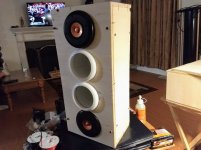
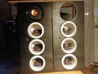
More progress on the enclosures. Sanding needed. More gluing. Screws will be gone in the final chapter. Using 1/2" plywood, very light. The little 3" drivers are already inside 3/8"-1/2" thick PVC, so very little damping needed for the box.
Next thing to complete is how to align each enclosure horizontally and vertically without disassembling the enclosures.
Cheers!
Attachments
I've finished both wood enclosures. Only thing left with these is to duplicate the rear panel, repaint, repaint and a final couple layers of polyurethane.
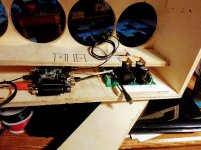
Today I completed mounting the 500W +-30V SMPS's and miniDIGI+miniDSP2x4 kits in each box. Also completed mounting the rest of the LM3886DR amps inside each PVC enclosure. Tight fit as you can see.
I have to order 2 more A5.2's, spray paint the white PVC gloss black and wire everything together. ETA, maybe 2 weeks for the listen.
Attachments
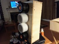
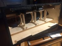
In the middle pic above there is 1 birch plank running along the outer circumference of the driver enclosure holes. There's another plank running on the opposite side. The idea was to 'pinch' the PVC enclosures tightly. But I've migrated to do things not too tightly and I'm thinking about lining the pinch planks with felt since I have some lying around.
Down below are pics that show the completion of this idea where I added 1/16" spacers. I made it so the 2 'pinch planks' can be removed in order to replace the SMPS or DSP circuit boards when necessary.
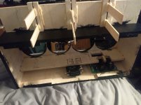
This past week the last two A5.2 drivers arrived.
Today I:
1) Paint the remaining PVC enclosures gloss black using Krylon plastic spray.
2) Make the flanges for the remaining 6 enclosures. This is the most difficult part!
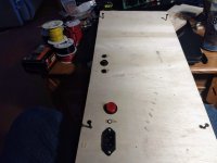
3) Start wiring the power in section, i.e. EMI filter, circuit breaker, power button & SMPS power in. Also the 15V/GND from SMPS to DSP boards.
4) Mark all drivers L (1..3) & R(1..3).
Down below are pics that show the completion of this idea where I added 1/16" spacers. I made it so the 2 'pinch planks' can be removed in order to replace the SMPS or DSP circuit boards when necessary.
This past week the last two A5.2 drivers arrived.
Today I:
1) Paint the remaining PVC enclosures gloss black using Krylon plastic spray.
2) Make the flanges for the remaining 6 enclosures. This is the most difficult part!
3) Start wiring the power in section, i.e. EMI filter, circuit breaker, power button & SMPS power in. Also the 15V/GND from SMPS to DSP boards.
4) Mark all drivers L (1..3) & R(1..3).
Attachments
- Status
- This old topic is closed. If you want to reopen this topic, contact a moderator using the "Report Post" button.
- Home
- Loudspeakers
- Full Range
- Alpair 5.2 mini array for rear 4 channel per side