Chris, I read somewhere here on DIYAudio you recommending Tom's Done Right Amps, so I checked them out and am very pleased. I just recently realized the input sensitivity of the Done right Amps is .95Vrms, which is identical to the miniDSP feeding them audio. This issue has very recently come up in another subwoofer project I'm working on, and the Amp input sensitivity is not matched to what is driving it...
Still to be resolved is the mounting scheme, might go the way of the P7 array with magnetic attachment or something else I have in mind...
Anyway, Happy Birthday! I just happened to glance down on the homepage.
Still to be resolved is the mounting scheme, might go the way of the P7 array with magnetic attachment or something else I have in mind...
Anyway, Happy Birthday! I just happened to glance down on the homepage.
... I just recently realized the input sensitivity of the Done right Amps is .95Vrms, which is identical to the miniDSP feeding them audio. This issue has very recently come up in another subwoofer project I'm working on, and the Amp input sensitivity is not matched to what is driving it...
EDIT:Added embedded link above.
Thanks, guys. Had a great family dinner last night - more modest and less strain on digestive system than sister Julie’s reliably Dionysian spreads- and a light breakfast this morning with my mom & wife. This afternoon we’re out to other sister’s place for third and final shattering of ashes of step dad who passed away a year ago this month. That kinda puts the impermanence of our physical selves in perspective - but no further maudlin prattling.
Thanks for not getting all maudlin on us Chris! Enjoy the holidays all.
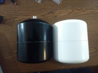
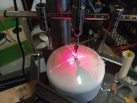
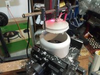
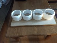
The first 2 original units that've been completed were made out of 5" PVC manufactured in the US. The other 6 units are 5" PVC made in China. I had no choice as the US stock was out when I ordered a few weeks ago. There is a slight difference in the curvature, shown below. On a good note, the inside of the China endcap there is a molding mark indicating center. Today I'll drill the holes for the drivers and make the flanges for the remaining 6 enclosures.
When it comes time to order the drivers, I am marking L & R to keep track of left and right drivers. They come matched from MarkAudio when ordered in pairs. Sadly, this is something I failed to do for the larger arrays. The A5.2 drivers will be the final pieces to be ordered. BTW, anxiously waiting here in the US for the new A*MS drivers to be available!
Also, today I ordered all the components for LM3886DR amps. Also ordered a nice $40 plastic 2U 19" rackmount case that will house the (2) +-30V 500W SMPS's and the (2) miniDIGI+miniDSP2x4 combo kits. Since I'm using SPDIF optical inputs on the miniDSP boards and the pass-thru from the 1st to the 2nd, the first miniDSP board's output will have to be delayed by 2.88ms according to the manual. This is one of the functions built into the 2x4 Advanced programmable plug-in. The resolution is .02ms. it's a very impressive little $80 board IMO, but good luck finding the miniDIGI boards, which handles the SPDIF I/O.
Here's a pic of the curvature difference between US & China manufacturers. Focus on the rear where the connector is on the completed unit (left) as I've not yet drilled the hole for the driver in the front (right).
Attachments
Last edited:
Thanks, still working......Seriously, this should be a very interesting system.
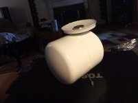
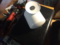
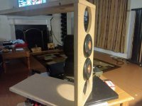
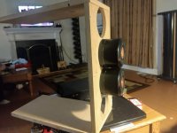
Here's how I'm thinking of magnetically mount these enclosures. There's an N52 magnet in the middle of the PVC I use from cutting out the hole for the A5.2 diver. This is how I did the 12/side P7 Array. After a year the N52 are still going strong on 3/8" thick steel. The magnets don't actually touch the metal but they're very close.
Attachments
Dr1v3n,
Remind me, that is a focused array ?
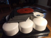
There is that possibility right? Early on with the 12x P7 array I shaped it into a concave shape but didn't notice that much of a difference. So now there all just pointed straight ahead. With just 4 drivers it makes sense to have positioning variable for experimentation.
More pix!
Attachments

When I played with focused arrays, the 4 x 4" driver (5" frame) was very very vertical directional compared to 9 unit using same sized drivers.
Based on that and your observations, perhaps the more the drivers, the less critical.
Wiith your magnets, you can easily play, good idea.
My only concern is that they will walk around as time passes.
Nice work.
Based on that and your observations, perhaps the more the drivers, the less critical.
Wiith your magnets, you can easily play, good idea.
My only concern is that they will walk around as time passes.
Nice work.
Thanks Bob for your observations!
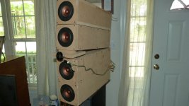
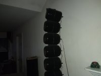
I have some old pics before I finally wound up with my 12x P7 PVC arrays. Like you, I definitely noticed a 'sweet spot' in the vertical plane from a listening position about 6ft away when using 4x P7...
Tonight maybe I'll find the energy to make some flanges...
Happy New Years!
I have some old pics before I finally wound up with my 12x P7 PVC arrays. Like you, I definitely noticed a 'sweet spot' in the vertical plane from a listening position about 6ft away when using 4x P7...
Tonight maybe I'll find the energy to make some flanges...
Happy New Years!
Attachments
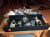
Progress report,added to inventory:
2 more A5.2's. This leaves 4 to get.
Components for 6 LM3886DR's.
1 2U rack mount enclosure for SMPS's & DSP.
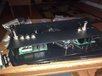
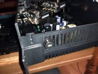
Been really focusing on the 2U RM enclosure and placing boards, drilling holes etc. I am liking how it is coming about. One detail I am realizing is the length of the cables will have some voltage drop. Originally I intended this system for a small room, i.e. 3ft cables. These cables are the +-30V and RCA audio signals to the speakers which house the LM3386DR's using 20AWG stranded wire. I think initially I will aim for 20Ft so I can also do testing in a larger room...
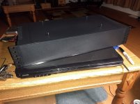
Here's some pics of the Power/DSP box. I'm waiting on more connectors and the 20AWG spools to complete it.
I am also working on way to mount these PVC enclosures. Will most likely lose the magnet idea, for multiple reasons.
2 more A5.2's. This leaves 4 to get.
Components for 6 LM3886DR's.
1 2U rack mount enclosure for SMPS's & DSP.
Been really focusing on the 2U RM enclosure and placing boards, drilling holes etc. I am liking how it is coming about. One detail I am realizing is the length of the cables will have some voltage drop. Originally I intended this system for a small room, i.e. 3ft cables. These cables are the +-30V and RCA audio signals to the speakers which house the LM3386DR's using 20AWG stranded wire. I think initially I will aim for 20Ft so I can also do testing in a larger room...
Here's some pics of the Power/DSP box. I'm waiting on more connectors and the 20AWG spools to complete it.
I am also working on way to mount these PVC enclosures. Will most likely lose the magnet idea, for multiple reasons.
Attachments
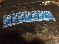
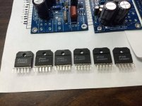
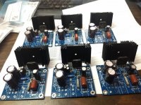
Only component left to complete these 6 amps is the custom output inductor, L1.
In the right pic I'm sizing up the heat sinks I've chosen for Tom's LM3886DR amps. They need to be custom cut in order to fit over the cap's and the board.
In the left pic I took a close up of the date/production codes of the chip amps I purchased from eBay. Not one matches another...
In the right pic I'm sizing up the heat sinks I've chosen for Tom's LM3886DR amps. They need to be custom cut in order to fit over the cap's and the board.
In the left pic I took a close up of the date/production codes of the chip amps I purchased from eBay. Not one matches another...
Attachments
- Status
- This old topic is closed. If you want to reopen this topic, contact a moderator using the "Report Post" button.
- Home
- Loudspeakers
- Full Range
- Alpair 5.2 mini array for rear 4 channel per side