Hey Guys,
I am trying to understand how I can model loudspeakers in LTspice with their electrical equivalents.
I found these spice models by Duncan Munro.
Loudspeakers
.SUBCKT VINT30 A B
R_RL A $N_0002 7.5
R_RD1 $N_0002 $N_0003 12.5
L_LD1 $N_0003 $N_0002 20mH
C_CD1 $N_0002 $N_0003 250u
R_RD2 $N_0003 $N_0004 0.5
C_CD2 $N_0003 $N_0004 50u
L_LD2 $N_0004 $N_0003 100uH
L_LD3 B $N_0004 100uH
R_RD3 B $N_0004 20
.ENDS
I know I can paste this .SUBCKT statement in LSspice and it would do all the dirty work for me but I specifically want to build to the whole model from Spice components. Below I will Attach a Speaker simulation I found on another forum from someone building an active load box for a guitar amplifier, I guess what they are aiming to do is simulate the parasitics of a loudspeaker and how its impedance changes with frequency -the same as this .SUBCKT model would try and emulate as well-.
Can I substitute the values in this .SUBCKT model into my active load circuit?
if so where does everything go?
What measurements can I do on my own loudspeakers to create an electrical equivalent model of my own?
Attachments
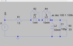
If you look at the sub-circuit you'll see it has two terminals, A and B.
It then shows a list of components with type (R, L, C), nodes connected to (A, $N_0002), and value (7.5, 20mH)
What I did here is put the terminals on the schematic with the 'label net' command and set them as port type 'input'.
Then I went down the list of components and added each one in.
Starting with the 7.5 ohm resistor I see it shows connections to A and $N_0002, so I connected one end to the A terminal, and labeled the other end as 0002 with the 'label net' command, port type as 'none'. This lets me keep track of each node.
the next component is a resistor from $N_0002 to $N_0003 so that connects to node 0002 on one side, and I labeled the other side 0003. Keep adding in the parts so that each one is connected to the nodes as shown in the list. Parts that show the same two nodes as each other are in parallel.
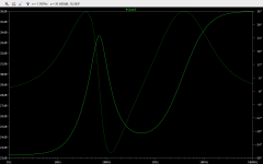
As a demonstration I added a current source with AC amplitude set to 1 under advanced settings and connected it between A and a ground, then connected B to ground. I set the simulation command to AC Analysis, octave, 200 points per octave from 1Hz to 100KHz. Run the simulation, probe terminal A. On the right of the graph right click and turn off plot phase, on the left of the graph right click the scale and change it to logarithmic and it will show impedance in ohms.
It then shows a list of components with type (R, L, C), nodes connected to (A, $N_0002), and value (7.5, 20mH)
What I did here is put the terminals on the schematic with the 'label net' command and set them as port type 'input'.
Then I went down the list of components and added each one in.
Starting with the 7.5 ohm resistor I see it shows connections to A and $N_0002, so I connected one end to the A terminal, and labeled the other end as 0002 with the 'label net' command, port type as 'none'. This lets me keep track of each node.
the next component is a resistor from $N_0002 to $N_0003 so that connects to node 0002 on one side, and I labeled the other side 0003. Keep adding in the parts so that each one is connected to the nodes as shown in the list. Parts that show the same two nodes as each other are in parallel.
As a demonstration I added a current source with AC amplitude set to 1 under advanced settings and connected it between A and a ground, then connected B to ground. I set the simulation command to AC Analysis, octave, 200 points per octave from 1Hz to 100KHz. Run the simulation, probe terminal A. On the right of the graph right click and turn off plot phase, on the left of the graph right click the scale and change it to logarithmic and it will show impedance in ohms.
Attachments
Last edited:
Thank you Radtech! This is extremely helpful.
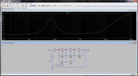
I just realized that this is actually just three filters (R2,L1,C1), (R3,L2,C2) and (R4,L3)that sums over Rload(R1). Does this mean that this is just an emulation of the frequency response of a vintage 30, or is it an accurate electrical equivalent?
I just realized that this is actually just three filters (R2,L1,C1), (R3,L2,C2) and (R4,L3)that sums over Rload(R1). Does this mean that this is just an emulation of the frequency response of a vintage 30, or is it an accurate electrical equivalent?
I'm not an expert on speakers, or their emulation so I can't really say for sure.
I am reasonable good at LTSpice though
Speakers are complicated things and models have to take into account not only the electrical properties of the coil but also the effects of magnetism and mechanics which can act like electrical components, I believe this is where the large capacitances in the models come into play.
There are many threads on the topic, e.g., a recent one: Spice Modeling Acoustic Properties of Speakers
- Status
- This old topic is closed. If you want to reopen this topic, contact a moderator using the "Report Post" button.
- Home
- Loudspeakers
- Full Range
- Loudspeaker Norton//Thevenin electrical equivalents and LTspice models