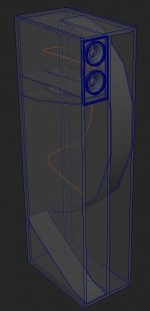
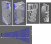
Based on the info on Folded horn speaker design - explanation and calculator I modeled a folded back loaded horn box for two 3.5" full range drivers.
I initially modeled one targeting 100hz as the low-frequency resonance, but it was inconveniently large(70"h, 16"w, 24"deep) so I then targeted 200hz which resulted in a more reasonable size box(42.5"h, 9.5"w,16"deep).
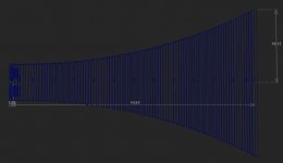
The horn unfolded is 4"wide the full length, 54.6" long, 8" tall at the throat, 33.5" tall at the mouth.
I've never done this before, so am interested in feedback, like if there's something obviously wrong with the design.
I initially modeled one targeting 100hz as the low-frequency resonance, but it was inconveniently large(70"h, 16"w, 24"deep) so I then targeted 200hz which resulted in a more reasonable size box(42.5"h, 9.5"w,16"deep).
The horn unfolded is 4"wide the full length, 54.6" long, 8" tall at the throat, 33.5" tall at the mouth.
I've never done this before, so am interested in feedback, like if there's something obviously wrong with the design.
Attachments
Last edited:
Really need driver specs and frequency response, so will just say that normally one wants a BLH's HF response to peter out by ~125-250 Hz depending on the app, ergo a 200 Hz cutoff implies it will horn load way too high up in the mids, causing too much out of phase comb filtering with the driver's forward output if not heavily damped, negating most of the horn's high efficiency output.
GM
GM
Right, but that said, these type drivers tend to be high Q, so short of the necessary specs....... go 'old school' DIY and do an inverted BIB pipe horn designed based on a 140 Hz Fs, Vas, Qts juggled to get a 70 Hz BIB with a ~96"^2 Sm will probably work well enough and constructing it out of a fairly rigid cardboard box material with hot glue will help to damp it without the need for excessive stuffing.
GM
GM
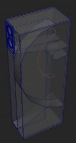
I have modified the gamma on your images to make them easier to see.
There is a lot of wasted space in this design. As well one does not need to keep smooth curves. That will allow more unwanted high frequencies to get to the mouth where combing with the direct response will cause combing.
And as GM points out with a BLH one wants to keep the HF response of the horn part to be limited… 250-300 Hz is as high as practical, doing a 200 Hz makes no sense.
WHile the article you point to may be a reasonable primer, it is not all that good a tool for designing horns. There are some good software tools that allow good estimates of what real world response will be.
It is certainly possible to get decent LF from a small “horn”. FH-Lite is an example. Wall/floor, or corner loading can be used to multiply the effective size of the mouth and the modeler will take TL action into account.
The Frugel-Horn
dave
Attachments
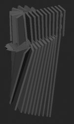
As the design sketch Dave posted above should by now quite familiar to frequenters of these fora, it should be noted that the FHL(ite) is designed for the approx 3" size range. While "scaling" a design to fit your individual requirement is not always successful this particular folding topology has proven to be very effective in two larger sizes, and for a wide range of drivers in each respective iteration.
While they appear deceptively simple, there was more than a little math involved on the part of Dr Scott.
While they appear deceptively simple, there was more than a little math involved on the part of Dr Scott.
Thanks for the response guys.
There's clearly a lot I don't understand here(particularly the comment about how smooth curves might be undesirable in this use case, implying that sharp angles dampen the HF output from the horn), and/or that article is way off on the math.
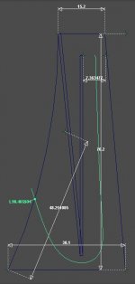
For instance, if I apply the function from here to the Frugel-Horn I get a LF resonance of ~352.33 hz, and the length should be 150cm vs the ~98.46cm that results in the illustration above.
There's clearly a lot I don't understand here(particularly the comment about how smooth curves might be undesirable in this use case, implying that sharp angles dampen the HF output from the horn), and/or that article is way off on the math.
For instance, if I apply the function from here to the Frugel-Horn I get a LF resonance of ~352.33 hz, and the length should be 150cm vs the ~98.46cm that results in the illustration above.
Attachments
Last edited:
The FH-Lite is good to about 60 Hz or so.
Indeed the math in that article is only rudimentary. And there is theory and real-world. Real world is more complex. The decent modelers do much more complicated math, and have been adjusted/tweaked to match real-world builds.
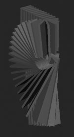
Do note that the Frugel-Horn has at least a 4x multiplication of the mouth size because of the proximity to a wall/floor junction. And if the green line is supposed to represent the horn length how come it doesn’t wrap around th efold and reach to the end of th point?
dave
Indeed the math in that article is only rudimentary. And there is theory and real-world. Real world is more complex. The decent modelers do much more complicated math, and have been adjusted/tweaked to match real-world builds.
Do note that the Frugel-Horn has at least a 4x multiplication of the mouth size because of the proximity to a wall/floor junction. And if the green line is supposed to represent the horn length how come it doesn’t wrap around th efold and reach to the end of th point?
dave
I put the start of the line where the speaker is and figured the folded space behind it that lead nowhere was some sort of baffle since the sound isn't likely to travel down in and back up and round in a way that results in amplifying anything.
I could be way off base though.
I could be way off base though.
again, thanks for replying Dave.
I'm thinking sound waves as ripples in water. Maybe that's a poor comparison.
If it was water ripples though that enclosed area you're referring to, opposite the driver is only going to capture some of the energy, bounce it around till it's weaker before it makes it's way back around to the horn opening, also way out of phase from the ripples that traveled down the horn initially, damping and distorting those waves.
Does sound/ripples in air pressure behave that much differently?
In water sound travels faster...but we don't care.
What we care is the form of the wave, spherical in theory for perfection!, and how it gets distorted in the travel. At 20Hz we have 17 m wavelenght, 1.7m at 200 Hz
Those waves would then exit and meet the original wave, after being bended and all, and also being transmitted throuh the cabinet walls.

Only you can say. ")
Time is tight, but a handful of notes, FWIW.
-A horn is a pipe that expands toward the terminus. It may, or may not, be impedance-matched down to the QW cutoff frequency.
-The QW cutoff frequency is a function of the axial length and geometary.
-The frequency to which the horn is impedance matched is a function of expansion & ultimate terminus area, once any boundary loading is accounted for. As noted, these frequencies are not necessarily (rarely, with bass horns) one and the same, and in essence you are blending QW action with impedance-matched behaviour.
-There is no obligation that a drive unit should be located at the throat of the horn. In the case of chamberless horns, it may be tapped into the expansion path at x distance from the throat, which can be useful in suppressing undesirable harmonic resonances in a compromised (undersized expansion) horn.
-'Classic' horn formulas are accurate, but only if the horn is impedance matched down to the QW cutoff, i.e. the horn expansion is not compromised relative to length. In most cases for size reasons, bass horns are compromised in their expansion, or as a minimum, significant boundary loading.
-As has been noted, LF wavelengths are extremely long, and relatively unaffected by bends. As wavelengths get shorter (higher frequencies), so they become progressively more affected & attenuated. For back-loaded bass horns (i.e. those loaded by the rear of the drive unit) that is usually quite a good thing; they are only useful over a relatively narrow BW or group delay becomes excessive (and very audible). As an ROT, about 300Hz is a practical upper limit. Smooth expansion is nice, and technically it promotes maximum efficiency; however its greatest impact is in the shorter wavelengths at the top end of the horn's operating region, and, given the above, this is usually the place where you tend to want less rather than more efficiency. Some will disagree, but in general I tend to regard this as not worth the effort (and potentially counter-productive).
All this stuff and much more re TL, horn design are in MJK's, Prof. Leach's docs and this website:
Quarter Wavelength Loudspeaker Design
https://leachlegacy.ece.gatech.edu/papers/HornPaper/HornPaper.pdf
Resonance Concepts
GM
Quarter Wavelength Loudspeaker Design
https://leachlegacy.ece.gatech.edu/papers/HornPaper/HornPaper.pdf
Resonance Concepts
GM
- Status
- This old topic is closed. If you want to reopen this topic, contact a moderator using the "Report Post" button.
- Home
- Loudspeakers
- Full Range
- Folded Back Loaded Horn Design