The build I'm currently working on, is a modification of an array of 8 MA Pluvia 7's that's in my sig. Pic's there too. Those enclosures were made of 3/4" MDF.
I was initially going to START experimenting with 4x 4in PVC 2ft long sealed enclosures. With a coupler on the front end, the diameter of the P7 frame would fit perfect. But some have said that this would not allow for any diffraction, which I don't disagree with. But I have a new idea, a vented design. PVC lends itself to many possibilities due to all the piece configurations that one can mix and match.
My idea for a vented design to address the lack of diffraction issue is to have a concentric larger 6in PVC pipe surrounding the P7 mounted to an internal 4in pipe, which is open on the back end. Externally there would be a 6in PVC pipe, open on the front but centered, and on the back end would be a 6in PVC cap. These caps are rounded internally BTW. Screws would be used along the outer body to center the 'floating' 4in internal tube.
So there would be about a 1/2in gap around the P7 where the lower frequencies would surround the upper frequencies and everything would exit out of the front.
Any thoughts? Bad idea? Terrible idea? Or maybe possible? I'd like to post pics if get into this.
Last edited:
Venting has nothing to do with baffle diffraction. When you mount a driver inside a pipe like you originally described you get a circular baffle being the size of the drivers frame.
A circular baffle is the worst from a diffraction point of view i.e. it has the most. You can reduce it by making it into something closer to a hemisphere by using a bigger diameter pipe and putting a roundover from the edge of the frame to where it joins the pipe.
By doing that you will have the drivers further apart which isn't ideal but your whole "array" doesn't really conform in any other way so why start now")
Whether any of that matters is debatable, Linkwitz has the same setup with LXMini and Pluto and they were/are well regarded.
Perhaps you would be better off to test one and see if you like it more than the MDF one.
Is there something you are hoping to gain from changing the enclosures?
A circular baffle is the worst from a diffraction point of view i.e. it has the most. You can reduce it by making it into something closer to a hemisphere by using a bigger diameter pipe and putting a roundover from the edge of the frame to where it joins the pipe.
By doing that you will have the drivers further apart which isn't ideal but your whole "array" doesn't really conform in any other way so why start now
Whether any of that matters is debatable, Linkwitz has the same setup with LXMini and Pluto and they were/are well regarded.
Perhaps you would be better off to test one and see if you like it more than the MDF one.
Is there something you are hoping to gain from changing the enclosures?
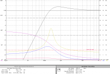
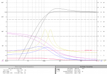
A “cylinder" difers from a hemisphere only in the size of the curvature at the edge. Olson’s baffle diffraction shows the change in FR at the baffle-step roll-off.
In this experiment the sphere did the best, later reseach showed it edged out by a teardrop shape. The cyclinder has 2 issues… the high ripple at bafflestep (about 3.3 kHz in this case) and the edge diffraction. With a cyclinder edge diffraction is all at the same time (on axis), but in this case it should not be a really big issue because the time delay is so low.
The solution isn’t to increase the pipe diameter, but to increase the edge radius and keep the drivers as close as possible…
I still think that a 4” pipe will cause too much early reflection back thru the cone.
dave
The solution isn’t to increase the pipe diameter, but to increase the edge radius and keep the drivers as close as possible…
Then how do you fabricate that "solution" out of a pipe?
It is impossible to increase the edge radius if the pipe only just about fits the drivers frame, any separate pipe enclosures can really only be close together or have increased edge radius (or roundover as I described it) not both together.
For a single driver the pipe makes some sense and the diffraction can be overcome or ignored, for an array I can't see how it is any better of an enclosure than what the OP already has.
The need for a solution in this scenario is driven by injecting a problem where one didn't already exist!
It was my understanding that the OP wanted them to be separate and was going to use them end on, which my comments are based on.
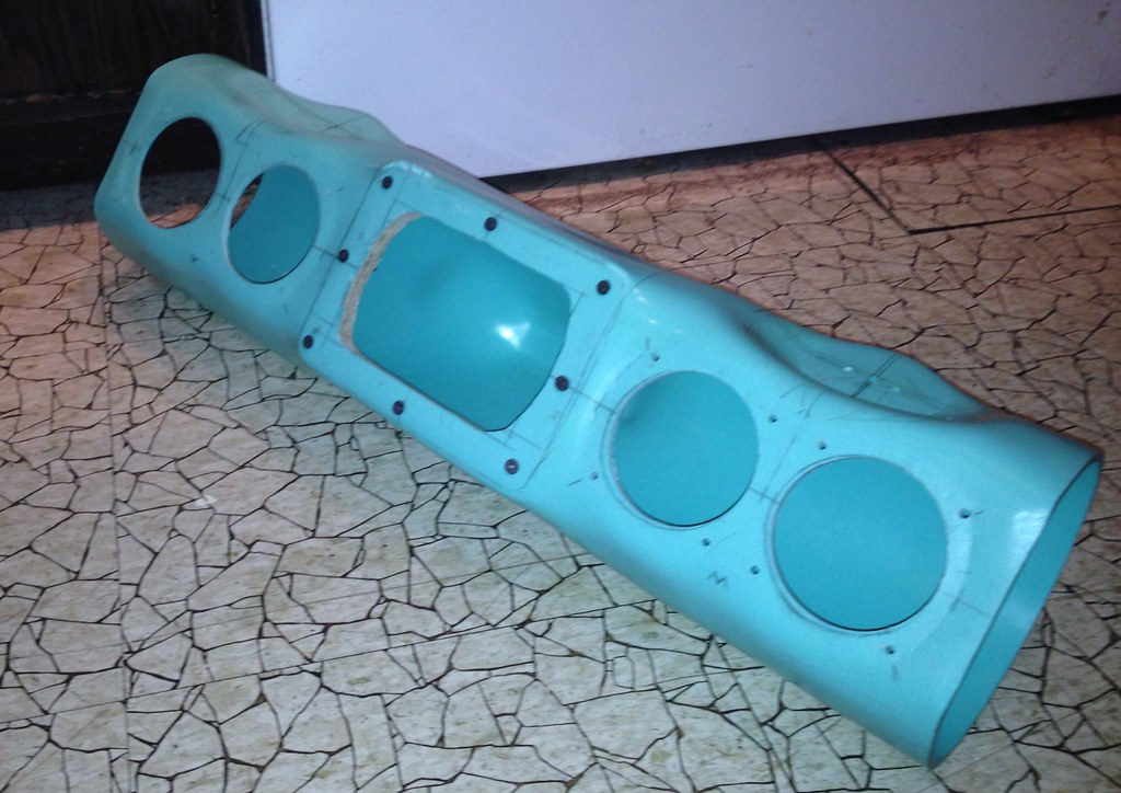
Certainly fantastic shapes can be made out of PVC if you have the skill or time to learn it. As seen above, turning that design to stand up and have cutouts for all the drivers would be a nice idea, probably would need to be a pretty big pipe to have enough volume though. Heat forming the pipe to have a flat mounting surface for the drivers is a very cool technique and gets around some of the difficulties of using a pipe for an array enclosure.
Certainly fantastic shapes can be made out of PVC if you have the skill or time to learn it. As seen above, turning that design to stand up and have cutouts for all the drivers would be a nice idea, probably would need to be a pretty big pipe to have enough volume though. Heat forming the pipe to have a flat mounting surface for the drivers is a very cool technique and gets around some of the difficulties of using a pipe for an array enclosure.
wanted them to be separate and was going to use them end on, which my comments are based on.
Morphing them would not rule that out. Trying to do it consistantly ovcer 16 pipes would take some jigs.
I’d take a page from the Scaena speakers and mostly just ignore the problems.
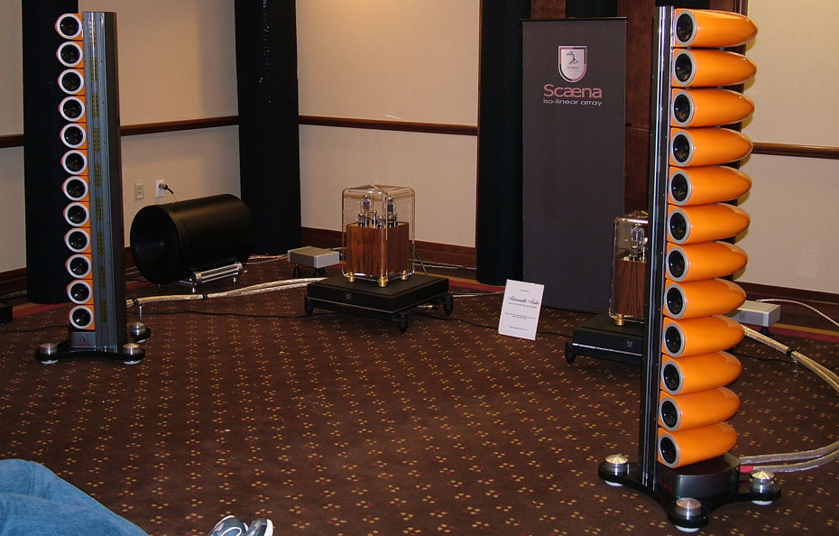
Use a 5” pipe, build a slighly rounded adaptor ring, and leave it at that. I’d leave the back open and damp them till aperiodic since there are woofers.
dave
Then how do you fabricate that "solution" out of a pipe?
Or a wood shaped donut glued over the end of the pipe. Make it wider than the pipe, shape it into a teardrop and place over the pipe.
More work, but not impossible using a manual lathe or cnc.
Doesn't help with c-c distance though...
Last edited:
Wow, thanks everyone for responding! This forum is great! Some really good knowledge here.
Forget about my original idea of concentric forward vented pipes. It was literally a 'pipe dream'.
Your responses gives me confidence to go ahead and get the 5" black PVC parts for 4 speakers to get this phase kickstarted.
I was hoping to get more drivers closer together. Even though each enclosure is angled, shaving an inch off of each one allows for at least 2 more enclosures for the 84in stands I'm using....Is there something you are hoping to gain from changing the enclosures?
Hmm, 5in would still be an advantage as my current boxes are 6in x 6in x 11in. And I could cut out the center of a round cap to achieve that hemisphere shape. Thanks for posting that Olson baffle diffraction pic, I've been looking for it but didn't know how to search for it....Use a 5” pipe, build a slighly rounded adaptor ring, and leave it at that. I’d leave the back open and damp them till aperiodic since there are woofers.
dave
Forget about my original idea of concentric forward vented pipes. It was literally a 'pipe dream'.
Your responses gives me confidence to go ahead and get the 5" black PVC parts for 4 speakers to get this phase kickstarted.
For a cutoff frequency of 150 Hz, would a volume of 2 litres be ideal?
Smaller than i would go.
dave
Attachments
Sorry my friend, I don't mean to ignore... Yes very similar to that design, except that I plan on using a rounded cap in order to mount the driver for the hemispherical front end, not flat like in your pics. AND I do prefer a 'light' tweeter in the middle of my array, like your MTM configuration. Probably just semantics, especially at louder SPLs, but it sounds really good so far in the rectangular boxes in my current setup.
Last edited:
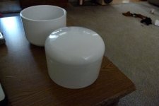
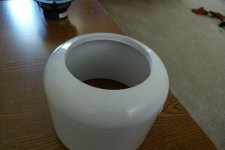
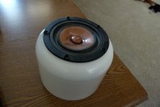
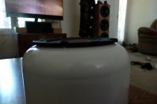
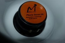
Got the 5" rounded endcaps in yesterday. Sorta disappointed the OD measures 6 1/8" or about 155mm. So I won't be able to have 14 drivers per side as planned. I'll have to settle for 12 drivers, which is ok, that's still 4 more per side which should be audibly noticeable. Still waiting on the 12" long tubes.
Once everything is in, I'll go back to the Pluvia 7 build in my sig. I'll also add this thread in there as maybe a 'Chapter 2'.
Here's some preliminary pics:
Once everything is in, I'll go back to the Pluvia 7 build in my sig. I'll also add this thread in there as maybe a 'Chapter 2'.
Here's some preliminary pics:
Attachments
- Status
- This old topic is closed. If you want to reopen this topic, contact a moderator using the "Report Post" button.
- Home
- Loudspeakers
- Full Range
- What do you guys/gals think of PVC for FR enclosure?