You've drawn a circuit in parallel to the driver, not series. Results may not be what you intend.New LCR notch, now 9.5 ohms // 4uF // 0.24mH (2 x 0.12mH in series).
It sounds better, to my ears this is not the 2.5KHz area which is annoying but around 8KHz.
Next I'll remove it because I ordered a DAYTON AUDIO DSP-408.
BUT
I use a tube amp with no feedback, DF is about 5 which is acceptable but a little bit low for this driver.
Is it a good idea to tame the Fs impedance in this case?
12mH inductors are affordable (20eur) and if capacitor film is prefered, it's possible to find some 47uF for cheap (18 in //).
Does it worth it?
Parallel LCR is alright for driver resonance peak compensation. The values look plausible.
Emk2, you decide. Do you notice peaking around 48Hz? If not, you don't need to change anything.
The resonance peak reduces current draw at it's frequency. This results in less voltage drop in the output resistance of your amp, increasing voltage hence more volume at that point.
Often, the peak is left uncorrected to increase bass extension.
In a typical system, with an amplifier output impedance of a fraction of an Ohm, a circuit in parallel to the driver can have no effect. The amp is a voltage source, it shorts the added circuit out.Parallel LCR is alright for driver resonance peak compensation. The values look plausible.
Emk2, you decide. Do you notice peaking around 48Hz? If not, you don't need to change anything.
The resonance peak reduces current draw at it's frequency. This results in less voltage drop in the output resistance of your amp, increasing voltage hence more volume at that point.
Often, the peak is left uncorrected to increase bass extension.
I use a tube amp with no feedback, DF is about 5 which is acceptable but a little bit low for this driver.
Is it a good idea to tame the Fs impedance in this case?
Gazza,
Emk2 is using no ideal voltage source. I take that the damping factor that he/she mentions is related to 8 Ohms, thus the amp's output impedance becomes 1.6 Ohms.
An externally hosted image should be here but it was not working when we last tested it.
Thank you ")
Calculation is based from this:
Series Notch Filter Designer / Calculator Help
But result is different from this one:
HiFi Loudspeaker Design
Actually there is only a parallel LCR in series with the driver to tame the 5-10KHz zone. It seems to be effective.
I'll have to do some measurements again to confirm but bump is more at 80-100Hz than at Fs (48Hz).
Seems to be usual, probably a mix of room effect and too small enclosure (about 90L BR in my case).
Attachments
Yes, I'll use the DSP for the 80-100Hz bump too.
My question was: even if there is no bump at Fs (about 48Hz for this driver), is there a possible benefit to tame the Fs resonnance in case of an amplifier with a non-negligible output impedance? or if there is no bump, just leave as is.
My question was: even if there is no bump at Fs (about 48Hz for this driver), is there a possible benefit to tame the Fs resonnance in case of an amplifier with a non-negligible output impedance? or if there is no bump, just leave as is.
small enclosure (about 90L BR in my case).
Wait a second, 48Hz is the free air resonance. In a BR box, you should get two bumps, but neither at 48Hz. Please measure impedance first.
What the parallel LCR does, when used correctly, is to consume energy at a certain frequency band, so the current draw from the amp is about the same as at other frequencies. Audible benefit, other than correcting frequency response? Don't know.
That is unlikely to be the case across the audio spectrum. The result will be variable and unpredictable.Gazza,
Emk2 is using no ideal voltage source. I take that the damping factor that he/she mentions is related to 8 Ohms, thus the amp's output impedance becomes 1.6 Ohms.
An externally hosted image should be here but it was not working when we last tested it.
I'd like to see some data on this.That is unlikely to be the case across the audio spectrum. The result will be variable and unpredictable.
I'd like to see some data on this.
The impedance of the load is unlikely to be 8 ohms across it’s frequency range. The output impedance of the amplifier and the load impedance will form a varying (with frequency) voltage divider, thus varying the voltage level to the load, and therefore varying frequency response.
SS
What he said.The impedance of the load is unlikely to be 8 ohms across it’s frequency range. The output impedance of the amplifier and the load impedance will form a varying (with frequency) voltage divider, thus varying the voltage level to the load, and therefore varying frequency response.
SS
Gazza, I get it, it though seems we are talking of different things. The amplifier output impedance is the one that is the basic problem here. The damping factor is usually given for a constant load, but is sure no frequency invariant value in reality.
I assume that the source impedance be constant, which may be not always true. Capacitance and inductance from output transformers or filters and coupling capacitors is certainly a possibility. That's what I would like to see any data on.
The speaker impedance is varying of course, this is well known, and can be calculated, in small signal domain at least. With passive filters, we usually assume that to be the case. Is this your critique?
The problem is, if you measure everything at a specific frequency, you could design and implement what you want. But move away from that frequency and it all goes to hell. The amps output Z, without feedback, will certainly be changing. And then you decide to try a different amp... Whoah. Down the drain.Gazza, I get it, it though seems we are talking of different things. The amplifier output impedance is the one that is the basic problem here. The damping factor is usually given for a constant load, but is sure no frequency invariant value in reality.
I assume that the source impedance be constant, which may be not always true. Capacitance and inductance from output transformers or filters and coupling capacitors is certainly a possibility. That's what I would like to see any data on.
The speaker impedance is varying of course, this is well known, and can be calculated, in small signal domain at least. With passive filters, we usually assume that to be the case. Is this your critique?
For a practical approach, you got to take chances... Amps are measured into ohmic loads, loudspeakers are measured with low impedance, and we'll never know what the final result will be without testing.
Then again, the point of impedance compensation is to linearise the loudspeaker circuit (make it behave more like a resistor, so to say), so that variance in amp impedance are minimised. If you have a better idea what to do, other than use low output impedance amps, let us know. I am looking forward to emk2's measurements.
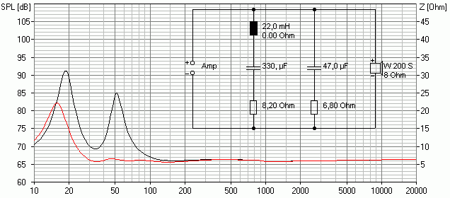
See this example for an 8" driver in a vented box. The parallel LCR reduces the variance at the upper system resonance, the RC compensates for the speaker's inductance.
Then again, the point of impedance compensation is to linearise the loudspeaker circuit (make it behave more like a resistor, so to say), so that variance in amp impedance are minimised. If you have a better idea what to do, other than use low output impedance amps, let us know. I am looking forward to emk2's measurements.
See this example for an 8" driver in a vented box. The parallel LCR reduces the variance at the upper system resonance, the RC compensates for the speaker's inductance.
Last edited:
Still waiting for jack 6.35mm connectors, when received, I'll try to measure the Fane impedance.
Dayton DSP 408 received, nice little box, seems to be well made, silent and good preamps (with EQ flat, I don't hear any difference with or without the DSP).
First, the beginner mistake: not a good idea to "flat" the whole 20-20K band
It sounds dull, muffled.
Second try, which immediately led me to the following conclusion: why didn't I buy a DSP before
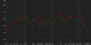
REW screenshot of left channel (red) and right (green), umik-1 at listening position (about 3 meters) before EQ.
Speaker enclosure was a mistake, I wanted to try a small one (95L, 60cm x 60cm x 30cm), a lot of damping inside helped.
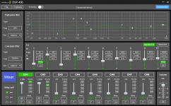
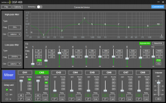
And screnshots of Dayton DSP 408 software.
I am a beginner so EQ is probably not optimal from 1K-10K range.
Dayton DSP 408 received, nice little box, seems to be well made, silent and good preamps (with EQ flat, I don't hear any difference with or without the DSP).
First, the beginner mistake: not a good idea to "flat" the whole 20-20K band
It sounds dull, muffled.
Second try, which immediately led me to the following conclusion: why didn't I buy a DSP before
REW screenshot of left channel (red) and right (green), umik-1 at listening position (about 3 meters) before EQ.
Speaker enclosure was a mistake, I wanted to try a small one (95L, 60cm x 60cm x 30cm), a lot of damping inside helped.
And screnshots of Dayton DSP 408 software.
I am a beginner so EQ is probably not optimal from 1K-10K range.
Attachments
Been there too, equalize for on axis doesn't cut it. The off axis behavior of the Fane is very complex.
What I'd do, if I ha a DSP: certainly notch out the 1.7kHz peak, also cut a bit at 4 and 6.5 kHz. These are resonances in the most delicate area of hearing, thus need attention. Equalizing the balance in the 400Hz and 5...13kHz ranges seems appropriate. Otherwise, add some broad EQ to taste...
I enjoy my stuff currently just using tone controls. Being aware of the limitations of that approach, I actually did not clearly notice the 1.7k bump until a few days ago I listened to Jennifer Warnes' "Famous Blue Raincoat" album, in which she hit that area well...
- Home
- Loudspeakers
- Full Range
- New 15" full range - FANE