I'm trying to get my head around how beamforming works in the audio context, and am starting to wonder whether there might be a decent dose of smoke and mirrors involved.
Full disclosure. My day job is as an electronics engineer working in the radio astronomy field. The instrument I work on is one of the larger radio telescopes globally (and growing). Modern radio telescopes make great use of beamforming, both at the focus of antennas with parabolic dishes and directly with aperture plane arrays.
I've built a straightforward four-element linear array, using Vifa TG-9 3.5" full range drivers, with an element spacing of 90mm. Initially I started by throwing a single driver in a 1l cubic sealed box and measuring it. It measured surprisingly well for its size, and I found that by adding some equalisation using a minidsp I was able to extend the bottom end beyond fs to around 60-70Hz, albeit with a significant rise in distortion limiting it to use at low levels. The four way array is a natural progression of that experiment, and as expected that gives me 6dB improvement in distortion performance at the bottom end.
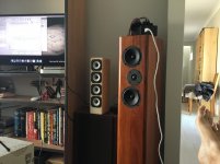
The quick and dirty test enclosure is pictured. It's 8 x 13 x 40cm internal, built from 9mm MDF with a 16mm ply baffle and some bracing on the sides.
So when measuring it with no equalisation I expected to see a grating lobe coincident to the 90mm element separation, with holes at ~2KHz, corresponding to 1/2 wave at the element spacing.
Despite much care, I wasn't able to discern any real dip moving my microphone around.
This puzzled me. I'm used to things being much more clear-cut. At first I thought I might be being stymied by multipath, and I guess I probably am - my environment is complex. But I wonder if the real issue is that the drivers themselves are not point sources, being ~8cm across, leading to rather a lot of smearing.
I went and read some web pages describing Bessel arrays (A Paul Kemble web page - speaker bessel arrays.), trying to reconcile the material presented with my own knowledge of beamforming at microwave frequencies. The amplitude and phase relationships between drivers presented appears rather arbitrary, and doesn't have any concept of broad-banding, where the phase is varied with frequency. I simply don't understand it. Rather than creating a phase-coherent source I think that the arbitrary sticking some drivers in reverse and halving the power for others would just further break up any coherence that forms.
I wonder if perhaps the real issue here is that when we do beamforming at UHF and microwave frequencies, we keep the element spacing under 1/2 wavelength to satisfy nyquist. To do that at audio frequency implies a maximum diver size of under 10mm. So whatever we do we're not going to get a point source.
Full disclosure. My day job is as an electronics engineer working in the radio astronomy field. The instrument I work on is one of the larger radio telescopes globally (and growing). Modern radio telescopes make great use of beamforming, both at the focus of antennas with parabolic dishes and directly with aperture plane arrays.
I've built a straightforward four-element linear array, using Vifa TG-9 3.5" full range drivers, with an element spacing of 90mm. Initially I started by throwing a single driver in a 1l cubic sealed box and measuring it. It measured surprisingly well for its size, and I found that by adding some equalisation using a minidsp I was able to extend the bottom end beyond fs to around 60-70Hz, albeit with a significant rise in distortion limiting it to use at low levels. The four way array is a natural progression of that experiment, and as expected that gives me 6dB improvement in distortion performance at the bottom end.
The quick and dirty test enclosure is pictured. It's 8 x 13 x 40cm internal, built from 9mm MDF with a 16mm ply baffle and some bracing on the sides.
So when measuring it with no equalisation I expected to see a grating lobe coincident to the 90mm element separation, with holes at ~2KHz, corresponding to 1/2 wave at the element spacing.
Despite much care, I wasn't able to discern any real dip moving my microphone around.
This puzzled me. I'm used to things being much more clear-cut. At first I thought I might be being stymied by multipath, and I guess I probably am - my environment is complex. But I wonder if the real issue is that the drivers themselves are not point sources, being ~8cm across, leading to rather a lot of smearing.
I went and read some web pages describing Bessel arrays (A Paul Kemble web page - speaker bessel arrays.), trying to reconcile the material presented with my own knowledge of beamforming at microwave frequencies. The amplitude and phase relationships between drivers presented appears rather arbitrary, and doesn't have any concept of broad-banding, where the phase is varied with frequency. I simply don't understand it. Rather than creating a phase-coherent source I think that the arbitrary sticking some drivers in reverse and halving the power for others would just further break up any coherence that forms.
I wonder if perhaps the real issue here is that when we do beamforming at UHF and microwave frequencies, we keep the element spacing under 1/2 wavelength to satisfy nyquist. To do that at audio frequency implies a maximum diver size of under 10mm. So whatever we do we're not going to get a point source.
Attachments
Try to move the microphone up beyond the top speaker, not only to the left and right.
The center to center spacing might be 90mm, the (acoustic) centre of each driver to the microphone will be less. Moving the microphone above the array will change that.
Coming from someone with arrays of 25 TC9 drivers each with a centre to centre distance of ~85 mm.")
The center to center spacing might be 90mm, the (acoustic) centre of each driver to the microphone will be less. Moving the microphone above the array will change that.
Coming from someone with arrays of 25 TC9 drivers each with a centre to centre distance of ~85 mm.
Yes, as I move well out of the axis of the speaker I get a broad reduction in treble, which is worse than that for the single speaker. But where on-axis for the single speaker is a small vertical range, on axis for my little array is extended to my 36cm, so there's a good region where I can stick my head (these speakers will probably be used alongside my monitor as glorified computer speakers) and be essentially on-axis.
Just wondering, with your line array do you drive elements individually, or in groups, or do you drive the whole lot with one amplifier? And if so, do you do any of this phase reversal stuff? I can see the single-amplifier case with everything in phase working well and creating a roughly linear wavefront in the vertical, but doing anything else would just break that wavefront up and make it chaotic.
Just wondering, with your line array do you drive elements individually, or in groups, or do you drive the whole lot with one amplifier? And if so, do you do any of this phase reversal stuff? I can see the single-amplifier case with everything in phase working well and creating a roughly linear wavefront in the vertical, but doing anything else would just break that wavefront up and make it chaotic.
Maybe this will help: https://web.archive.org/web/20070221101021/http://www.audiodiycentral.com/resource/pdf/nflawp.pdf
GM
GM
Quasi-Anechoic Measurement of Loudspeakers Using Beamforming Method is a paper that describes a measurement technique that uses a delay-sum beamforming method to suppress (noisy) room reflections. The idea is that one takes multiple measurements along a straight line moving the measurement microphone in small step increments along the line. The direct sound does not change much along the line, but the reflections do change with each mic position. Therefore, by summing the measurements, the direct sound is highly correlated, but the unwanted reflections are uncorrelated, and when summed are suppressed. The more measurements, the higher correlation of the direct sound and the greater suppression of the uncorrelated reflections.
I took 10 measurements, moving the microphone in 10 cm increments before and after the top of the equilateral triangle at the listening position. The paper explains the rest.
In the chart below, the green curve is the average of the 10 measures and the red is a single measurement at the LP:
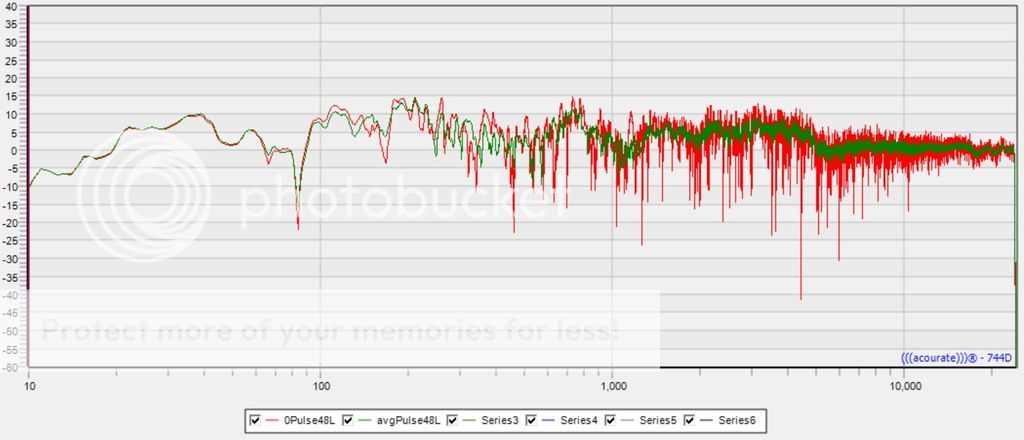
Using the average (green curve) for DSP eq correction results in a clearer sounding image at the LP, especially stereo cues, at least to my ears.
I took 10 measurements, moving the microphone in 10 cm increments before and after the top of the equilateral triangle at the listening position. The paper explains the rest.
In the chart below, the green curve is the average of the 10 measures and the red is a single measurement at the LP:
Using the average (green curve) for DSP eq correction results in a clearer sounding image at the LP, especially stereo cues, at least to my ears.
Yes, as I move well out of the axis of the speaker I get a broad reduction in treble, which is worse than that for the single speaker. But where on-axis for the single speaker is a small vertical range, on axis for my little array is extended to my 36cm, so there's a good region where I can stick my head (these speakers will probably be used alongside my monitor as glorified computer speakers) and be essentially on-axis.
Just wondering, with your line array do you drive elements individually, or in groups, or do you drive the whole lot with one amplifier? And if so, do you do any of this phase reversal stuff? I can see the single-amplifier case with everything in phase working well and creating a roughly linear wavefront in the vertical, but doing anything else would just break that wavefront up and make it chaotic.
I have 5 of them in series 5x parallel. They are corrected with FIR filters which boosts the low end. No Bessel arrangement is used. A lot more info can be found here.
It has become a huge thread but the first post has some pointers to various subjects of interest.
- Status
- This old topic is closed. If you want to reopen this topic, contact a moderator using the "Report Post" button.
- Home
- Loudspeakers
- Full Range
- Beamforming