Before investing any more coin on new enclosures, how about a little time and "shoe leather"? - i.e. there must be another DIYer within an easy day trip distance from you with a pair of A7s in something worth listening to.
It'll come as no surprise that I'd readily endorse the FH3 - if you have the requisite floor space -or the Pensils if more restricted. When operating full-range, I've always preferred this driver in a floorstanding enclosure - and certainly vented as opposed to sealed.
There are also a couple of small standmount/ bookshelf sized enclosures freely available here http://frugal-phile.com/boxlib/P10free/CGR-dMar-Ken73-190216.pdf , and perhaps Scott Lindgren also did a "Baby Lab" for them as well? The last is just a guess - he and Dave had been very busy, and I'd certainly not seen every single design drawing, nor even built more than a few score of them. I currently don't have access to Dave's office and computer on which such plans might reside.
Thanks Chris
http://wodendesign.com/downloads/Woden-BabyLabs-081015.pdf
It's difficult to find someone who interested in this type of hobby
 so anyone in the UK based in north london who is using Alpair 7's in a good sounding enclosure let me know, i would be interested in hearing them.
You agree that the FH3 are good enclosures, i mean there kits are readily available and good value.
https://customcans.co.uk/s/s/index....ll-range-speaker-for-mark-audio-alpair-7.html
ill try and source someone on this forum who has a pair so i can go test them.
As for space, i can always make space, just got to deal with the wife!
That's very encouraging. The TL port extends bass down to 50Hz. Means little or no air leaks.
Can you provide cabinet dimension? In particular the TL cross section and taper.
The combined response should look decent. You need to place the speaker on a stand at least 1m from a wall and measure 1m out at mid height (driver : port) to get the combined response. Don't measure on a table, like your picture, it adversely effects the boundary between port and table.
Your TL design will be determined primarily by the driver, offset and TL cross section and taper. More bends and damping are refinements. The cabinet is only for <300Hz, the rest of the FR matches the data sheet.


Personally, I'd be interested in seeing measurements from something approximating your listening distance now

ok this was taken at standing head height in my listening position.
This does not look like its 1m from the speaker, at midway between driver and port. You need that distance to get a combined reading. It looks like you're measuring just the driver again. Is only the measured speaker being driven?
I measured A&C, did you mean measure from B?

I measured A&C, did you mean measure from B?
Yes, position B, with only the tested speaker being driven.
Is that the "red" last curve?
Last edited:
I measured A&C, did you mean measure from B?
Yes, position B, with only the tested speaker being driven.
Is that the "red" last curve?
Does it matter about the measuring volume?

Last edited:
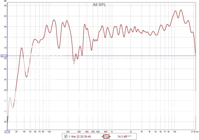
OK ,thanks I overlooked that one when I saw the first 2. It's an excellent graph, and the volume is fine at 80db as you're comfortably above the room noise levels (unless you live above a factory production line).
Ignore the dips at 45, 125, 245Hz these are most likely room acoustics. If you use REW, use the room acoustice tab and enter your room dimensions, then on the diagram place your speaker, and move the "head symbol" to your measuring position and you will see the predicted dips due to room acoustics. They will be off a few Hz as its hard to exactly predict wall and furniture absorption/reflection.
The combined response looks good with room acoustics. It looks like you have combined LF rolloff at around 50-60Hz which is fantastic for a smallish FR driver. Amazing really. If you want to approximate what your ear might react to, re-smooth to 1/3octave. We don't hear narrow bandwidth dips very well.
Your ears were correct, it probably sounds good, and you're the only one who's heard them. The speaker is working properly from the LF and HF responses. How many hours are on the drivers, have they been broken in (+20hrs).
OK ,thanks I overlooked that one when I saw the first 2. It's an excellent graph, and the volume is fine at 80db as you're comfortably above the room noise levels (unless you live above a factory production line).
Ignore the dips at 45, 125, 245Hz these are most likely room acoustics. If you use REW, use the room acoustice tab and enter your room dimensions, then on the diagram place your speaker, and move the "head symbol" to your measuring position and you will see the predicted dips due to room acoustics. They will be off a few Hz as its hard to exactly predict wall and furniture absorption/reflection.
The combined response looks good with room acoustics. It looks like you have combined LF rolloff at around 50-60Hz which is fantastic for a smallish FR driver. Amazing really. If you want to approximate what your ear might react to, re-smooth to 1/3octave. We don't hear narrow bandwidth dips very well.
Your ears were correct, it probably sounds good, and you're the only one who's heard them. The speaker is working properly from the LF and HF responses. How many hours are on the drivers, have they been broken in (+20hrs).
Well thats good news
those drivers were nicely broken in, they have had over 60 hours. Thanks for your time and support Don, you are certainly keeping me busy mate! Ok ill do as you say above, ill also test the other speaker which has the speaker wadding and compare them.
I think the Alpairs probably make this enclosure amazing, probably stick them anything and they'll sound great in some way.
Are they as deep as they look in your last photo, or is the image distorted?
not at all, click on the picture it should resize it. Ill post measurements soon.
Forgot to mention. When you start to add back the damping (stuffing) it will reduce that small high freq component (ripple) all over your FR. Damping will not change the overall shape but will make it smoother.Well thats good news
Ok ill do as you say above, ill also test the other speaker which has the speaker wadding and compare them.
I think the Alpairs probably make this enclosure amazing, probably stick them anything and they'll sound great in some way.
Start adding damping closer to the end of the TL first. Its more effective there, than at the driver end. You should also measure at the "B" position as you want to see the effect on the entire FR. This is really a trial and error process as you already know.
Forgot to mention. When you start to add back the damping (stuffing) it will reduce that small high freq component (ripple) all over your FR. Damping will not change the overall shape but will make it smoother.
Start adding damping closer to the end of the TL first. Its more effective there, than at the driver end. You should also measure at the "B" position as you want to see the effect on the entire FR. This is really a trial and error process as you already know.

Let me know what else you need, just quickly put this together
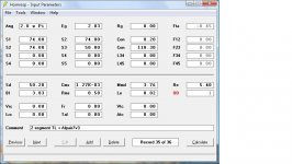
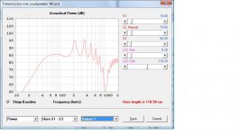
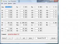
HornResp Model - Existing TL
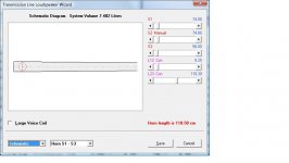
The TL has a simple taper and offset driver, there are no abrupt changes in cross section. So we can model it as a simple 2 section TL, which is good cause HornResp only does 5 sections max and no curvy things. The driver, taper, cross section and length will determine the performance. Bending is convenient but won't "drastically" change the prediction, same for damping.
I've put the non-damped output curves for both the driver and the port below that way you can compare them to the nearfield measurements you took. HornResp is not accurate for higher freq so compare <500Hz. Look at where the peaks and dips occur, they are the same as your TL. The magnitudes are a little larger because you don't have perfectly reflective even walls (real world). Your TL is working as designed, put the saw back in the case
Attachments
Last edited:
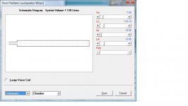
But can you make it into a Bass Reflex ??
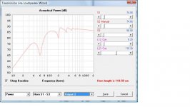
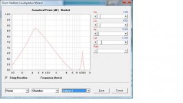
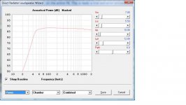
A comment came up earlier about making it into a Bass Reflex. Hmm,... wonder if that's possible. Well it turns out you can. The entire internal volume of your TL is 7.1L (5x13x110cm), that's enough volume with the right port. The right port is 3.6cm dia x 12cm at the end of the TL.
Take a block of styrofoam (don't scratch the wood) and make it a tight fit (jammed) in the mouth of the TL. Then place the pipe (3.6cm dia x 12cm) in the center of that styro block, assuming you've already made a hole for it. If you suspect air leaks use painters tape (green or blue) to seal the pipe and edges of the styro. Presto, you can test (ugh!) and compare the sound to a TL without commitment. Notice, the saw is still in the case.
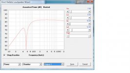
The pics below show a long BR with the driver output, port output and combined output.
A comment came up earlier about making it into a Bass Reflex. Hmm,... wonder if that's possible. Well it turns out you can. The entire internal volume of your TL is 7.1L (5x13x110cm), that's enough volume with the right port. The right port is 3.6cm dia x 12cm at the end of the TL.
Take a block of styrofoam (don't scratch the wood) and make it a tight fit (jammed) in the mouth of the TL. Then place the pipe (3.6cm dia x 12cm) in the center of that styro block, assuming you've already made a hole for it. If you suspect air leaks use painters tape (green or blue) to seal the pipe and edges of the styro. Presto, you can test (ugh!) and compare the sound to a TL without commitment. Notice, the saw is still in the case.
The pics below show a long BR with the driver output, port output and combined output.
Attachments
Last edited:
- Status
- This old topic is closed. If you want to reopen this topic, contact a moderator using the "Report Post" button.
- Home
- Loudspeakers
- Full Range
- Transmission Line Speaker Build using Alpair 7.3 speakers, first build.