I am trying a cone and dust cap "doping" treatment right now and am too excited too give the details! I am busy listening and will write more later. I think this may be "the FIX" for the HF ringing, glare and "distortion" I've been having. Right now; I'm running the Alpair 7P's straight to the amp.; no X/O, no woofers, no tweeters. Perfect? NO; much better? YES! I'm using item TDA-0006 "tacky speaker surround dampener and adhesive" available from Springfield Speaker LLC Springfield, Mo. Tacky Speaker Surround Dampener and Adhesive As I said, details later.
OK, still playing around here. There is a VERY fine line with these 7P's; they are extremely capable which means they are also "sensitive" to ANY changes no matter how small. I have been playing around with speakers 45+ years and I do believe these are some of the most neutral and revealing drivers out there; a real steal for the money! Anyway, any SLIGHT change can make a huge difference; not so true with less revealing drivers. Resistors, capacitors, inductors, internal wiring, cabling from the amplifier ALL need to be very high quality. Dave; you will be happy to know that this tacky glue CAN be partly removed if need be. I will provide more doping methods and details later; still fine tuning things but I really think this is the way to go. I am using my tweeters again now and woofers but the 7P's seem to have hit that "magic" place where no X/O is required!!???
Greetings Fella's,
Nipper, I really like how you thinking about this stuff. I'm into my 2nd year of DIYing...although hooked on music back in the mid 60's (had an uncle that worked for the local Hi-Fi shop...nothing like a little Harry Belafonte ringing through some Channel Master gear") ). So far in my DIY journey I have played around with some; MA CHP-70's, Vifa tc9's and a couple Beyma coaxial's. While I'm no where near the "tech level" that you guys are on, I'd sure like to be tagging along with this build. I have access to a shop, happy to be used and abuse me if I can help with the cause.
). So far in my DIY journey I have played around with some; MA CHP-70's, Vifa tc9's and a couple Beyma coaxial's. While I'm no where near the "tech level" that you guys are on, I'd sure like to be tagging along with this build. I have access to a shop, happy to be used and abuse me if I can help with the cause.
Mark
Nipper, I really like how you thinking about this stuff. I'm into my 2nd year of DIYing...although hooked on music back in the mid 60's (had an uncle that worked for the local Hi-Fi shop...nothing like a little Harry Belafonte ringing through some Channel Master gear
). So far in my DIY journey I have played around with some; MA CHP-70's, Vifa tc9's and a couple Beyma coaxial's. While I'm no where near the "tech level" that you guys are on, I'd sure like to be tagging along with this build. I have access to a shop, happy to be used and abuse me if I can help with the cause. Mark
Tacky glue updates. Don't over do it! Place the drivers so that the cones are facing upwards and leave them in this position until the glue is totally cured (it will turn clear, remember, this is tacky glue, it will always be "sticky" to the touch). Start with a little treatment; let it dry then do some listening tests because everyone's tastes will be different. I tried an extra thick second layer on the dust cap, THAT was a mistake; not only did "good" treble suffer but the bass got too loud and boomy. Luckily; I was able to remove most of this "excess" before it fully cured. Here is what I did to start: with a small artist's paint brush, apply a medium-thin amount of tacky glue to the dust cap; about half the diameter in the center area ONLY. Do NOT let it drip down the sides of the cap to the junction with the cone. If this DOES happen; remove this immediately. Apply medium-thin tacky glue around the cone. I did an area about 3/8 to 1/2 inch (circular, doesn't have to be an actual true circle). Do this in 6 separate places all around the cone. These glue areas are small enough that they do NOT touch each other. They also do NOT touch the dust cap or the surround. This leaves enough un-treated paper cone material so that the sound character remains true to the original YET, the highest frequencies are under much better control. Once the glue is cured; try a listening test. If you still think there is too much (un-wanted) high frequency harshness; apply glue to the areas BETWEEN the original treated areas up to and including the junction with the surround. Do NOT do this in the direction of the dust cap; leave those areas un-treated. OK, that's what I did. IF you want to try this, BE CAREFUL. Better to try things in small stages than to over apply glue and not be able to recover. Everyone's listening tastes are different; as Dave pointed out, some people aren't even aware or sensitive to some of these HF, Hi-Q ringing or resonant issues. To play it safe, try smaller treatment areas first; do your listening tests then add extra treatment areas if needed.
Can you sketch a diagram of where you put it on the cone. Are the spots over or between the ribs on the back of the cone?
dave
Hi again; unfortunately, I don't have a digital camera or I would take some photos. I have no (known) means of doing a sketch electronically either. I did not take into account the location of the ribs or any other structure on the back-side of the cone. I'll try to describe it better. Think of the area of the cone BETWEEN the surround and the dust cap. My glue blobs are all approximately the same size and there are six of them approximately equally spaced around the central area of the cone. As I said, they do NOT touch each other nor do they touch the dust cap or surround. If you want; I could draw with pencil and paper a sketch then mail or fax it to you. Sorry, low tech. PC! (UNLESS, do you know of a free download software I could try that would allow me to do a sketch???).
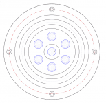
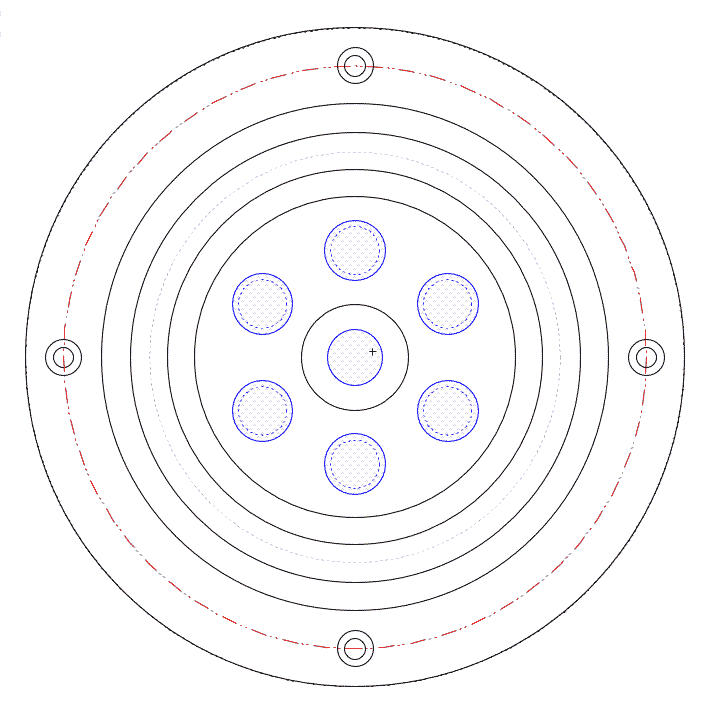
Like this?
dave
yep! Start smaller if you like. Mine are actually a little larger but that is the pattern indeed! Now, if that doesn't do it; my 2nd treatment was to go between these 6 areas up to and including the junction with the surround but ONLY the OUTER 1/3rd or so. I didn't add any other glue area in the direction of the dust cap.
I wish I could do this under laboratory conditions as a controlled experiment with laser based vibration analysis and precision measurements!!! That way, we could attack the offending vibrating region or regions and leave everything else alone.
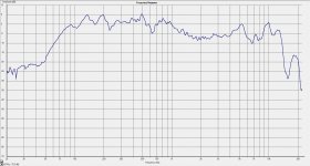
If you have a good calibrated microphone and some test tones, you may want to do this in very small stages; trying just a few treatment areas at a time. I "think" the problem area is the small peak you see in the OEM FR around 8KHz but I don't know that for sure. I DO know my problem is MOST obvious at the highest violin notes; somewhere in the harmonics or overtones from about 6KHz to 12KHz. In most of my crossovers I tried; 12KHz would already be at least 3 dB down but doesn't necessarily mean the problem couldn't be higher!??
Best of luck!
I am very interested in your results from selective doping of the Mark Audio paper drivers. I bought a pair of CHN70 drivers as possible drivers for a Auratone type mix box.
They are completely unsuited to this role as they play far to high and far to deep. However having put them in a smallish ported enclosure to have a look see at their behaviour, I became interested by thier response.
A measurement showed they behave much more like the response of the plastic basket drivers than their published spec. They have a similar peak arround 5k and 12k.
When I first put them on they sounded awful but with something quite interesting going on, they felt like they had more to give and the very spitty mumbled response was a artefact of the enclosure.
The mumbled response was I think down to internal cabinet reflections and resonance. They seem to be extreemly sensitive to physical mounting and the cabinet I plonked them in was not great. A wadge load of panel damping material including competley covering the baffle and they started to tramsform. They still seemed to be suffering with mid range confusion so I filled the cabinet with baff wadding leaving a bit of clear air behing the driver. This seems to have solved that problem and reduced the Q of the port which even out the bass response a bit as well.I am guessing but the very light paper cone might be quite suseptable to refections upsetting it.
The spitty sound has massively reduced with only a few hours of play back. I even went and checked against my active monitors to check it wasnt just me aclimatising to the sound.
They are still a little bright and can be sibalant on female vocal and over stridant strings but enable me to hear things in the mix I was previously unaware of. I can’t remember the track but I was clearly able to hear where an overdub had been cut in on one song which I had never heard before so they are clearly doing something very well.
Another thing I noticed is they seem to have a good power response in the room, other than a small loss of HF if you walk out of the room the sound still remains well balanced without significant tonal shifts.
I paid £42 for a pair shipped, for this they seem like a massive bargain and I plan to use them as near field monitors for my computer as being full range and having good off axis response they seem ideal for this.
Hence if the only remaining quible the HF peaks can be resolved with a little of the right glue in the right place I am very keen to hear your results.
Last edited:
I am very interested in your results from selective doping of the Mark Audio paper drivers. I bought a pair of CHN70 drivers as possible drivers for a Auratone type mix box.
They are completely unsuited to this role as they play far to high and far to deep. However having put them in a smallish ported enclosure to have a look see at their behaviour, I became interested by thier response.
A measurement showed they behave much more like the response of the plastic basket drivers than their published spec. They have a similar peak arround 5k and 12k.
When I first put them on they sounded awful but with something quite interesting going on, they felt like they had more to give and the very spitty mumbled response was a artefact of the enclosure.
The mumbled response was I think down to internal cabinet reflections and resonance. They seem to be extreemly sensitive to physical mounting and the cabinet I plonked them in was not great. A wadge load of panel damping material including competley covering the baffle and they started to tramsform. They still seemed to be suffering with mid range confusion so I filled the cabinet with baff wadding leaving a bit of clear air behing the driver. This seems to have solved that problem and reduced the Q of the port which even out the bass response a bit as well.I am guessing but the very light paper cone might be quite suseptable to refections upsetting it.
The spitty sound has massively reduced with only a few hours of play back. I even went and checked against my active monitors to check it wasnt just me aclimatising to the sound.
They are still a little bright and can be sibalant on female vocal and over stridant strings but enable me to hear things in the mix I was previously unaware of. I can’t remember the track but I was clearly able to hear where an overdub had been cut in on one song which I had never heard before so they are clearly doing something very well.
Another thing I noticed is they seem to have a good power response in the room, other than a small loss of HF if you walk out of the room the sound still remains well balanced without significant tonal shifts.
I paid £42 for a pair shipped, for this they seem like a massive bargain and I plan to use them as near field monitors for my computer as being full range and having good off axis response they seem ideal for this.I recommend
Hence if the only remaining quible the HF peaks can be resolved with a little of the right glue in the right place I am very keen to hear your results.
Basically, I'm done with my experiments. I am very happy with my results but that doesn't mean others shouldn't try my ideas with different variations. I recommend to ANYONE; start off with small areas first and do listening tests between dopings. If you do small, thin coats; the drying time is less than a few hours.
Before you finish with us here nipper, could you check your spot orientation wrt the radial stiffeners on the back?
dave
As your drawing exists; rotate your pattern about 30 degrees (CW or CCW obviously doesn't matter). None of my original 6 glue area "centers" are directly in-line with the mounting holes (ie, NOT directly over the "spokes"). I didn't take any back-side structure into account when I did this; I just made it up free-hand style.
BTW, I just got back from a live symphony orchestra performance of Mahler's 7th. I was in the front row; could literally almost reach out and touch the violin section....SO; as I call it, I've just had my hearing re-calibrated ha ha ha! One could spend millions of dollars on very high-end equipment and still never equal the sound of a real live performance in a world class auditorium!
I WILL continue to check this thread from time to time as enough people now seem to be interested in my doping method.
Cheers to all !
As your drawing exists; rotate your pattern about 30 degrees (CW or CCW obviously doesn't matter). None of my original 6 glue area "centers" are directly in-line with the mounting holes (ie, NOT directly over the "spokes"). I didn't take any back-side structure into account when I did this; I just made it up free-hand style.
When you get a chance, please check the spots wrt the ribs… I believe there are 6 ribs so they won’t line up with th eboly holes either.
dave
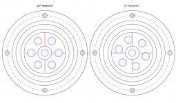
I just looked at the drawing. Rotating the driver 90° would result in the same layout of the spots as rotating the spots 30°.
dave
I cannot easily remove my drivers but there are only 4 "spokes" as I call them which are located 90 degrees apart and centered at each of the 4 mounting holes. So, having 6 equally spaced areas 60 degrees apart gives us our 360 degrees. What I'm saying is if you draw a (imaginary) straight line from a mounting hole to it's opposite (180 degree); this line is also directly over 2 opposite spokes. SO, none of my 6 areas have their center directly over these imaginary lines. Your drawing shows 2 of the 6 glue areas centered along this imaginary line from opposite mounting holes. What I'm saying is if you rotate your pattern 30 degrees, NONE of the six glue area centers will be over the 4 spokes.
Am I missing something here in what you're saying or asking?
OK, very sorry, now I get it! It's been a very long day for me; way past my bed-time so I'm nearly brain dead! HAH! Yes, obviously a "spot" located at 60 degrees rotated CW 30 degrees would then be at 90 degrees! Again, sorry! SO, if you're concerned having a spot centered directly over a spoke will be an issue; rotate by some other angle. You might also consider doing 7 areas instead of six. I basically had the idea to leave spacing between the treated areas; six is not a magic number by any means. I think if you do only say 5 areas, the treatment area "might" be too large though!??. Of course, you could make it in the shape of an oval or elipse . The main idea was to have several areas of equal size but not so large as to touch or overlap in any way.
… there are only 4 "spokes" as I call them which are located 90 degrees apart and centered at each of the 4 mounting holes. So, having 6 equally spaced areas 60 degrees apart gives us our 360 degrees… Your drawing shows 2 of the 6 glue areas centered along this imaginary line from opposite mounting holes. What I'm saying is if you rotate your pattern 30 degrees, NONE of the six glue area centers will be over the 4 spokes.
Am I missing something here in what you're saying or asking?
Yes you are missing something. If you have 4 radial ribs on the back (your spokes — i looked at them but never counted them) and 6 spots then 2 of them still fall on the ribs if rotated 30°, and will at least touch if rotated 15°. Here rotated:
dave
Attachments
- Status
- This old topic is closed. If you want to reopen this topic, contact a moderator using the "Report Post" button.
- Home
- Loudspeakers
- Full Range
- Alpair 7P (paper) experiences (so far)