Your eye is off by a few microseconds as the measurement was done at 48K so the ringing is probably closer to the 24K half sample limit. Good deduction on the timing but not outboard DSP just the DAC filter which could be considered to be internal DSP
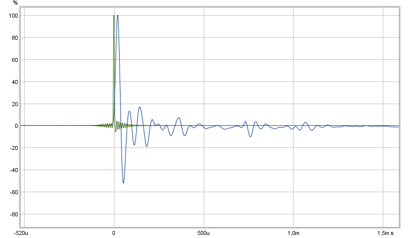
We first need to determine if the "ringing" is an artifact of the speaker array, the amp, or the DSP, but IMO it does not matter. I am counting roughly 4.5 oscillations over a period of 200 microseconds. That gives a wavelength around 44 microseconds.
1/.000044s = 22,500Hz, so this "resonance" is above the range of human hearing and should be completely inaudible, whether caused by the speakers, amp, or DSP is irrelevant. And my rough estimate by eyeballing the graphs is right at half the sample rate of 44.1kHz CD audio or 22.05kHz, so the 22kHz ringing is very likely a DSP artifact.
")
There has been so many posts recently that you might have missed it but he already posted a comparison of his Behringer vs the one he is using in the TC9 measurements, and there is more post ringing when I look at it.
Post here
http://www.diyaudio.com/forums/full...c9-line-array-cnc-cabinet-47.html#post5090456 ...
Sorry fluid if from that post it doesn't stand clear that first two IR is pure loopback of USB soundcard UMC204HD and third IR is acoustic TC9 with AP192 soundcard chain and its better looking filtering, that filtering is present as loopback into post 501.
Fluid, BYRTT has many tricks up his sleeve
(and many audio devices to play with...)
I should have looked at the image I linked more closely as it actually says TC9 in the legend
 Byrtt tricked me by putting it next to the Behringer loopback impulse
 Byrtt what does the impulse from that card look like without the dividing?
...Byrtt what does the impulse from that card look like without the dividing?
None of my IR is divided with anything except the lower one for speaker system at post 497.
None of my IR is divided with anything except the lower one for speaker system at post 497.
Admit for TC9 measurement more dividing could be used because there sits a Behringer Xenyx mic preamp and old Luxman integrated amp into chain that is not loopback benchmarked and calibrated into REW, but think those would change things very little because soundcard domain is cut at 96kHz and mic preamp from input to main out of mixer (Xenyx 802) have spec <10Hz-160kHz +0dB/-3dB. Correction file for mic is present into REW at that TC9 measurement time so REW can make its own dividing there.
I plan to try a few different EQ schemes to see what the difference is. I like the idea of the beamforming measurement technique where the results are spatially averaged rather than frequency windowed. The new REW beta has a few tricks to make that a bit easier which is good news. Given that I won't have any room treatment I doubt a single point measurement will cut it...
Agree that technique sound promising and nice new features into REW, could also imagine down the road when arrays are placed inside your living room that if sharing mdat file with wesayso he would polite help get EQ correction so as your arrays at listening position would get close to his performance minus the differences as room treatment and virtual Haas Kicker.
Really nice and interesting reading. Really like the parallell/series discussion of drivers in same enclosure.
Just a question: Is this curved linearrays or just straight line, no individual time delay?
Ref curved line array:
http://www.jblpro.com/ProductAttachments/CBT_Tech_Note_Vol1No35_091007.pdf
Just a question: Is this curved linearrays or just straight line, no individual time delay?
Ref curved line array:
http://www.jblpro.com/ProductAttachments/CBT_Tech_Note_Vol1No35_091007.pdf
Really nice and interesting reading. Really like the parallell/series discussion of drivers in same enclosure.
Just a question: Is this curved linearrays or just straight line, no individual time delay?
Ref curved line array:
http://www.jblpro.com/ProductAttachments/CBT_Tech_Note_Vol1No35_091007.pdf
Straight, no time delay, no amplitude shading
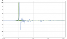
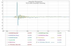
I removed the IR delay and put the soundcard impulse against the TC9 measurement and you can see where the ringing lines up and it rings for just over 500usec.
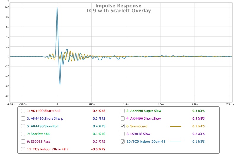
Byrtt do you have a measurement of the TC9 with the Behringer soundcard as the ringing does look to be very similar?
Another thing that was surprising is that the calibration of an onboard soundcard you posted in the rephase thread also had very little ringing in comparison.
When the soundcard is calibrated the frequency response and phase are compensated in a following measurement of the same device but the impulse response looks identical.
Do you think that dividing the calibration to end up with a pulse and then using that somehow to remove the ringing from the soundcard and see just the speaker response would work?
I posted the frequency response and phase plots of the different AK4495 filters in this thread
http://www.diyaudio.com/forums/digital-line-level/287835-dual-mono-ak4495s-ak4137-mcu-lcd-dac-kit-160-a-32.html#post5091813
Also surprising that they measure quite differently but the sound is not drastically changed for any of them.
Attachments
Your eye is off by a few microseconds as the measurement was done at 48K so the ringing is probably closer to the 24K half sample limit. Good deduction on the timing but not outboard DSP just the DAC filter which could be considered to be internal DSP
The latest graphs also show ringing with constructive and destructive interference ripples. If there is a 44100 <-> 48000 conversion anywhere in the chain, then ringing near half the sample rate will cause moire patterns. Or possibly 22050Hz and 24000Hz waves interfering will do this causing amplitude modulation. Any two notes of equal magnitude and close in frequency will constructively and destructively interact.
The latest graphs also show ringing with constructive and destructive interference ripples. If there is a 44100 <-> 48000 conversion anywhere in the chain, then ringing near half the sample rate will cause moire patterns. Or possibly 22050Hz and 24000Hz waves interfering will do this causing amplitude modulation. Any two notes of equal magnitude and close in frequency will constructively and destructively interact.
I'm a bit confused as to what you are referring to, the image you quoted is Byrtt's with a 192kHz sample rate, that makes it a little harder to compare to mine at 48K.
Moire patterns is a video term to describe one form of aliasing, there are no 44 to 48 conversions in the loopback tests so I am a bit confused as to what you mean.
http://hometheaterhifi.com/technical/technical-reviews/up-sampling-aliasing-filtering-ringing-a-clarification-of-terminology/
This page has a pretty good explanation of aliasing and ringing, in fig 14 and the text around it it shows that the closer a filter is to a brickwall in the frequency domain the more it rings in the time domain. Even though the article is aimed at video it covers the aspects that affect audio too.
Then if anyone wants to read more about Fourier pairs, the chapter in the Scientist and Engineers guide to DSP has it
http://www.dspguide.com/ch11/1.htm
I probably should run some loopbacks on the Scarlett at different sampling rates to see how that affects the impulse response.
Last edited:
...Byrtt do you have a measurement of the TC9 with the Behringer soundcard as the ringing does look to be very similar?
Another thing that was surprising is that the calibration of an onboard soundcard you posted in the rephase thread also had very little ringing in comparison.
When the soundcard is calibrated the frequency response and phase are compensated in a following measurement of the same device but the impulse response looks identical.
Do you think that dividing the calibration to end up with a pulse and then using that somehow to remove the ringing from the soundcard and see just the speaker response would work?
I posted the frequency response and phase plots of the different AK4495 filters in this thread
http://www.diyaudio.com/forums/digi...137-mcu-lcd-dac-kit-160-a-32.html#post5091813
Also surprising that they measure quite differently but the sound is not drastically changed for any of them.
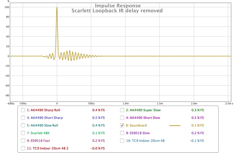
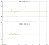
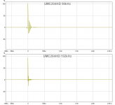
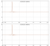
Have only loopback measurements for UMC204HD and find visuals below in same scale as yours, bit surprised they exactly the same even mine is another brand and 2ch in / 4ch out where yours is a lot more, from inside inspection of mine can tell its the famous asynchronous USB Xmos chip and Cirrus Logic ADCs/DACs in this interface. It looks problem is their coded filters at 44/48kHz if using 96/192kHz ringing gets much less. Don't no about Mac OS but in Windows OS shift REW to ASIO and 96/192kHz gets available settings. First below is UMC204HD at 44+48kHz and second UMC204HD at 96+192kHz, third is talked more about below.
Yes onboard ALC892 codec from RealTek on this Ivybridge generation computer is much better, even the still avaiable old very cheap 16bit UCA222/202 from Behringer is excellent into IR and actual also sounds very good when playing native CD material and i think xrk971 support me in this opinion, he have UCA202 which is relaxed silver painted and i have UCA222 which is bit alarming red. Find it bit strange why most old interfaces is perfect filtered by the book and many new ones show such tendency.
Agree using such ringing interface if we want to see speaker IR alone its better into REW not set a calibration file for that loop and instead add from a saved mdat-file that interface loop to current measurement session and divide.
Thanks sharing those DACs data will have a look.
Attachments
Don't stare at these IR's too long . In a speaker measurement you won't find the ringing of a DAC after the main pulse. It will be dominated by different frequencies and/or reflections of the driver itself. You'll only see the pré ringing part. What you're looking at is a combination of the entire frequency response. Though high frequencies usually dominate it's shape.
I'm not surprised you can't hear a difference between them when most of the ringing is above 20 KHz. It's good to know what you have, but there's a lot more data behind that IR rendering which is why there are so many ways to view the same data.
I'd say get familiar with all of the different tabs in REW to get a better understanding of what you're looking at. It's all the same data as in that IR.
. In a speaker measurement you won't find the ringing of a DAC after the main pulse. It will be dominated by different frequencies and/or reflections of the driver itself. You'll only see the pré ringing part. What you're looking at is a combination of the entire frequency response. Though high frequencies usually dominate it's shape. I'm not surprised you can't hear a difference between them when most of the ringing is above 20 KHz. It's good to know what you have, but there's a lot more data behind that IR rendering which is why there are so many ways to view the same data.
I'd say get familiar with all of the different tabs in REW to get a better understanding of what you're looking at. It's all the same data as in that IR.
It has been mentioned earlyer about overshoot and ringing.
If a low pass filter has Q over 0.5, a step response or impulse response will show this Q value as ringing. It actually is energy storage. To me it looks like the TC9 has some resonance/ energy storage before it falls off at HF.
There really is a lot of litterature on this as it is important when designing stable amplifiers and calculating phase margin.
Very similar probably are the same DAC chips. Thanks for the info 192 kHz may be the way to go. I will test that when I get the chance.Have only loopback measurements for UMC204HD and find visuals below in same scale as yours, bit surprised they exactly the same even mine is another brand and 2ch in / 4ch out where yours is a lot more, from inside inspection of mine can tell its the famous asynchronous USB Xmos chip and Cirrus Logic ADCs/DACs in this interface. It looks problem is their coded filters at 44/48kHz if using 96/192kHz ringing gets much less. Don't no about Mac OS but in Windows OS shift REW to ASIO and 96/192kHz gets available settings. First below is UMC204HD at 44+48kHz and second UMC204HD at 96+192kHz, third is talked more about below.
Yes onboard ALC892 codec from RealTek on this Ivybridge generation computer is much better, even the still avaiable old very cheap 16bit UCA222/202 from Behringer is excellent into IR and actual also sounds very good when playing native CD material and i think xrk971 support me in this opinion, he have UCA202 which is relaxed silver painted and i have UCA222 which is bit alarming red. Find it bit strange why most old interfaces is perfect filtered by the book and many new ones show such tendency.
Agree using such ringing interface if we want to see speaker IR alone its better into REW not set a calibration file for that loop and instead add from a saved mdat-file that interface loop to current measurement session and divide.
Thanks sharing those DACs data will have a look.
Ha Ha, very true.Don't stare at these IR's too long
Maybe, but the ringing is worse that I thought it would be and due to the length of it and the fact that it is very high in frequency means that it could well have an impact on the impulse view. As you say because it is so high it doesn't really show up in the other views unless you filter for it.In a speaker measurement you won't find the ringing of a DAC after the main pulse. It will be dominated by different frequencies and/or reflections of the driver itself. You'll only see the pré ringing part. What you're looking at is a combination of the entire frequency response. Though high frequencies usually dominate it's shape.
It was the speaker measurements that started it all off although that was really the weirdness before the peak which has now been laid to rest.
Not much of a difference, I can hear some difference between the filters on the AK but not all of them. Another case where the measurements look worse than the difference in sound. The slow filters in the AK do have quite a pronounced HF rolloff that can be seen in the frequency response measurements I posted in the DAC thread.I'm not surprised you can't hear a difference between them when most of the ringing is above 20 KHz. It's good to know what you have, but there's a lot more data behind that IR rendering which is why there are so many ways to view the same data.
Just a reflection on the SPL achivable when series/ parallell connecting.
Say you have 50 volt input signal. Then there is 50/5 = 10 volts on each element.
Lets say 85 dB at 2,83 volts and 97 dB at 10 volts.
Power summing of 24 element is 6 x 3 dB or 18dB gain. So max 115 dB
Think sweps are integrated over swep time to simulate pink noise in REW?
So the actual SPL when doing a sweep is about 20 dB less than the resulting SPL shown.
115 dB sin sweep is crasy loud and can damage the hearing.
130 dB sin sweep WILL damage hearing
It has been mentioned earlyer about overshoot and ringing.
If a low pass filter has Q over 0.5, a step response or impulse response will show this Q value as ringing. It actually is energy storage. To me it looks like the TC9 has some resonance/ energy storage before it falls off at HF.
There really is a lot of litterature on this as it is important when designing stable amplifiers and calculating phase margin.
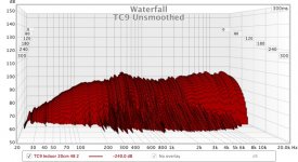
I'm not sure about that. The waterfall plot looks very clean to me. Here is an un-smoothed plot of an indoor measurement at 20cm.
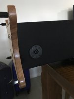
As it could be forgotten that this is a thread about a line array build I thought I would show what I have been up to today.
I felted the other speaker and put the socks on.
This is how the speakon looks on the back with the sock in place. Pretty happy with that.
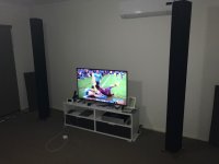
I have put them in living room in preparation for some listening, not the best photo but that's the best I can do tonight
Attachments
Just a reflection on the SPL achivable when series/ parallell connecting.
Say you have 50 volt input signal. Then there is 50/5 = 10 volts on each element.
Lets say 85 dB at 2,83 volts and 97 dB at 10 volts.
Power summing of 24 element is 6 x 3 dB or 18dB gain. So max 115 dB
Think sweps are integrated over swep time to simulate pink noise in REW?
So the actual SPL when doing a sweep is about 20 dB less than the resulting SPL shown.
115 dB sin sweep is crasy loud and can damage the hearing.
130 dB sin sweep WILL damage hearing
If all of that maths was due to the fact that the waterfall graph says 100dB then don't worry it was not taken at 100dB. The IR was exported and normalised before being re-imported so it could be compared to Byrtt's that had been recorded at a different level.
The max SPL depends on the EQ that is used. The more low frequency EQ is used the lower the overall max spl. Line array gain and increase in sensitivity is not across all frequencies so the overall limit before any eq is set by the ability of a single driver at the highest frequencies. Once you start EQ'ing the low frequencies you will run out of power or excursion before the single driver high frequency limit usually.
- Home
- Loudspeakers
- Full Range
- Full Range TC9 Line Array CNC Cabinet