So what's your plan for "wall integration"? It sounds like you could avoid the (very close) first reflection problems which have been troubling me over here: http://www.diyaudio.com/forums/mult...ine-array-lessons-learned-11.html#post4703810
Can you leave a space open in the corner, ie. not have studs meeting at the corner? It would be ideal to have the center line of the drivers exactly aligned to the corner.
Can you leave a space open in the corner, ie. not have studs meeting at the corner? It would be ideal to have the center line of the drivers exactly aligned to the corner.
Attachments
I haven't gotten that far into the details yet but was thinking about something similar to what RA7 had done but perhaps a bit closer to the corner through building some of the volume into the wall (albeit not the specific corner). That seemed like it would be pretty close to ideal but your idea could have potential as well. I'm not sure how much flexibility I have from a framing POV but I'll have the conversation with my GC!
Have you seen any one else do something similar? And is the benefit significant?
Have you seen any one else do something similar? And is the benefit significant?
So what's your plan for "wall integration"? It sounds like you could avoid the (very close) first reflection problems which have been troubling me over here: http://www.diyaudio.com/forums/mult...ine-array-lessons-learned-11.html#post4703810
Can you leave a space open in the corner, ie. not have studs meeting at the corner? It would be ideal to have the center line of the drivers exactly aligned to the corner.
I happened to run into my contractor this afternoon and he said that he can work with me on the framing of the corners. No big deal since that section of framing doesn't actually need to do anything significant structurally.
Here's my idea for how to do this:
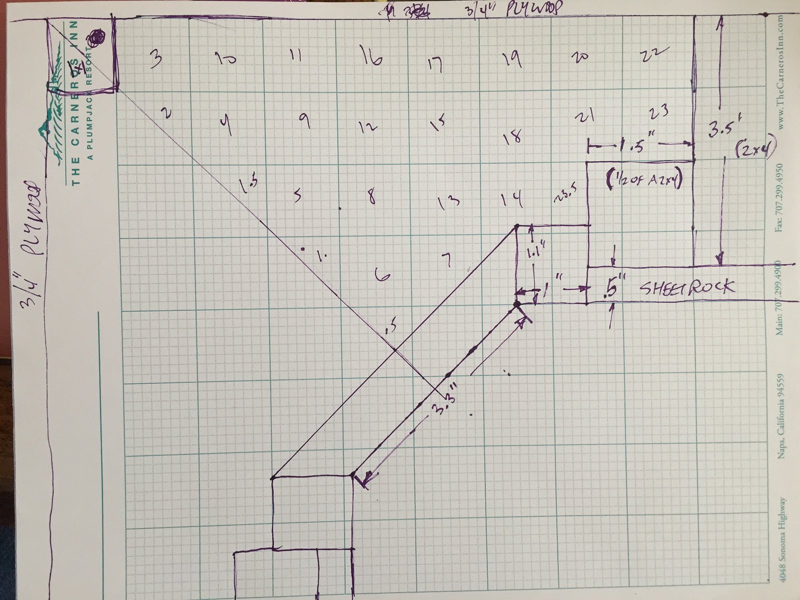
The front face of the 45 degree angle is a piece of 3/4" plywood 3.3" across, the same width as the squared off sides of the speaker basket. I would cut 45 degree angles to glue up to the 1.1"x1" square pieces. Those would in turn be glued to the framing which would be made up of a half a 2x4 which would be glued to a full 2x4 that makes up the "real" framing of the wall.
Also, on the backside (facing the garage and hallway), I'm thinking there would be 3/4" plywood screwed into the 2x4 framing along with a 1x1 support in the corner. I would be able to access the drivers from the rear through these panels.
That puts me at almost exactly 2.5L per driver (the numbered boxes are me taking the lazy way out to figure out sq in then multiplied by the 3.3" driver height and converted to L). And the drivers would be essentially flush with the walls minimizing reflections as much as possible effectively.
I'm not sure exactly how the interface with the sheetrock would work out... I guess they would tape and mud it. Also, I'm not sure how precisely the framers can build to this idea given it would need to be solid from floor to ceiling. So perhaps I could design in some "slop" either via slotted L brackets connecting the 1"x1.1" piece to the 2x4 or similar flexibility?
Would love upgrade ideas!
Here's my idea for how to do this:
The front face of the 45 degree angle is a piece of 3/4" plywood 3.3" across, the same width as the squared off sides of the speaker basket. I would cut 45 degree angles to glue up to the 1.1"x1" square pieces. Those would in turn be glued to the framing which would be made up of a half a 2x4 which would be glued to a full 2x4 that makes up the "real" framing of the wall.
Also, on the backside (facing the garage and hallway), I'm thinking there would be 3/4" plywood screwed into the 2x4 framing along with a 1x1 support in the corner. I would be able to access the drivers from the rear through these panels.
That puts me at almost exactly 2.5L per driver (the numbered boxes are me taking the lazy way out to figure out sq in then multiplied by the 3.3" driver height and converted to L). And the drivers would be essentially flush with the walls minimizing reflections as much as possible effectively.
I'm not sure exactly how the interface with the sheetrock would work out... I guess they would tape and mud it. Also, I'm not sure how precisely the framers can build to this idea given it would need to be solid from floor to ceiling. So perhaps I could design in some "slop" either via slotted L brackets connecting the 1"x1.1" piece to the 2x4 or similar flexibility?
Would love upgrade ideas!
In other news, I got DRC Designer to install via WINE. Are there tutorials or tips for DRC designer out there as well beyond what's in the main website?
Last edited:
I haven't gotten that far into the details yet but was thinking about something similar to what RA7 had done but perhaps a bit closer to the corner through building some of the volume into the wall (albeit not the specific corner). That seemed like it would be pretty close to ideal but your idea could have potential as well. I'm not sure how much flexibility I have from a framing POV but I'll have the conversation with my GC!
Have you seen any one else do something similar? And is the benefit significant?
Nope I've never seen it done! Did you see the simulations I linked to though? Some pretty smeary stuff going on from the close reflections with corner arrays, which you could totally avoid with a "in-wall corner" build. Could also put some absorbtion on the side/front walls at the reflection points (immediately next to the line) - that's what I'm planning on doing.
Here's my idea for how to do this:
The front face of the 45 degree angle is a piece of 3/4" plywood 3.3" across, the same width as the squared off sides of the speaker basket. I would cut 45 degree angles to glue up to the 1.1"x1" square pieces. Those would in turn be glued to the framing which would be made up of a half a 2x4 which would be glued to a full 2x4 that makes up the "real" framing of the wall.
Also, on the backside (facing the garage and hallway), I'm thinking there would be 3/4" plywood screwed into the 2x4 framing along with a 1x1 support in the corner. I would be able to access the drivers from the rear through these panels.
That puts me at almost exactly 2.5L per driver (the numbered boxes are me taking the lazy way out to figure out sq in then multiplied by the 3.3" driver height and converted to L). And the drivers would be essentially flush with the walls minimizing reflections as much as possible effectively.
I'm not sure exactly how the interface with the sheetrock would work out... I guess they would tape and mud it. Also, I'm not sure how precisely the framers can build to this idea given it would need to be solid from floor to ceiling. So perhaps I could design in some "slop" either via slotted L brackets connecting the 1"x1.1" piece to the 2x4 or similar flexibility?
Would love upgrade ideas!
Looks great! Why not use a 2x3 in place of the 2x2, lose the 1" piece and run the drywall right up against the angled piece? You would only have to fabricate the angled piece ahead of time and it can be mudded in and painted along with the walls. I would recommend countersinking for nice looks - best case, have the angled piece (baffle) CNC'd.
My guess is that this will work awesome.
") Very clean.
Very clean.
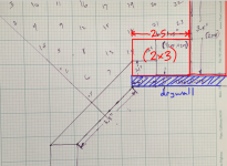
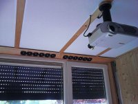
ah no, what i actually meant was like this. (attached)
doing the miter cut on the drywall should be avoided if possible!
rip the 2x3 out of a 2x4 to get a nice clean edge for the baffle to attach. the 2x3 can be toenailed into the adjacent 2x4 stud and plates on top/bottom. not sure how you were planning to attach the baffle to the framing. not critical really as long as there is an airseal. could build the whole corner apparatus and then nail it in at once. (ie, the surrounding 2x4's, 2x3's and baffle)
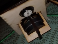
oh, one more thing make sure to allow airflow for the drivers on the back. that means a chamfer on the backside or some kind of interesting cutout shape (possible with CNC). attached another picture of the way i've been cutting out for the TC6 drivers.
doing the miter cut on the drywall should be avoided if possible!
rip the 2x3 out of a 2x4 to get a nice clean edge for the baffle to attach. the 2x3 can be toenailed into the adjacent 2x4 stud and plates on top/bottom. not sure how you were planning to attach the baffle to the framing. not critical really as long as there is an airseal. could build the whole corner apparatus and then nail it in at once. (ie, the surrounding 2x4's, 2x3's and baffle)
oh, one more thing make sure to allow airflow for the drivers on the back. that means a chamfer on the backside or some kind of interesting cutout shape (possible with CNC). attached another picture of the way i've been cutting out for the TC6 drivers.
Attachments
Last edited:


I agree on chamfering the back...
I've done this with a router and a template. So if CNC isn't an option you can still do it
Inspirational.. I've tried to do those chamfers leaving full-depth for the mounting holes (freehand) and it was a disaster, so yeah a template would help
Can't believe how much of your project you did with jigsaw and router. Would you actually recommend that course of action to others? I was planning a 3" hole saw and template for the router. I considered CNC for an aluminum baffle but I'm afraid of the cost. Besides, if for some reason the plywood version doesn't work out I can always scrap it for an upgrade if need be. Also, I think it will blend in better even though I admit the bling factor does appeal to me.
Another thought is to just use a thin sheet of aluminum (1/4") and go to town with a hole saw and no chamfers. I'd have to rethink how it attaches to the wall but it could solve a couple problems without being terribly expensive. Except perhaps in the number of hole saws I go through!
Another thought is to just use a thin sheet of aluminum (1/4") and go to town with a hole saw and no chamfers. I'd have to rethink how it attaches to the wall but it could solve a couple problems without being terribly expensive. Except perhaps in the number of hole saws I go through!
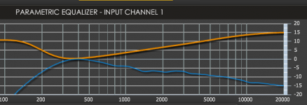
I made some measurements on my corner line arrays today which clearly show the effects of reflections.
From top to bottom:
- side wall and front wall treated
- only side wall treated
- no treatment
- simulation of first reflections from side and front wall
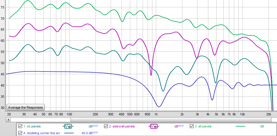
Even though you are using larger drivers closer into the corner, you could still have some of these problems. Not sure how to avoid that except for absorbtion. You could build some 2" panels into the corner perhaps, covered in white cloth. (or whatever matches the walls). Worth considering anyway.
From top to bottom:
- side wall and front wall treated
- only side wall treated
- no treatment
- simulation of first reflections from side and front wall
Even though you are using larger drivers closer into the corner, you could still have some of these problems. Not sure how to avoid that except for absorbtion. You could build some 2" panels into the corner perhaps, covered in white cloth. (or whatever matches the walls). Worth considering anyway.
Thanks for the heads up! I'm definitely planning on some treatments, but I will also do some measurements to see if they are even required at first. Given they'll really be literally in the corner, I can't see there being too much improvement from the front and side walls. But perhaps the opposite and back wall treatment would be more significant?
Also, looks like a 4"x89" piece (roughly the size I might need) would be about $70 each. So that's not too bad actually...
Is this the price for aluminum? Just for your info, I did a 2 piece baffle for a reason, so I could make it a sandwich with damping (and drivers) in between. Butyl rope works very well for that. (the back side towards the enclosure also has 4mm mass loaded vinyl on it and neoprene between enclosure and baffle)
Just to give you some ideas. I started with mass loaded vinyl and neoprene between both baffles, but the butyl rope worked way better damping the aluminum. Pick up a piece of aluminum and hit it. It will ring on it's own. It needs something.

- Status
- This old topic is closed. If you want to reopen this topic, contact a moderator using the "Report Post" button.
- Home
- Loudspeakers
- Full Range
- "Wall-integrated" corner loaded line array with Vifa TC9 drivers