This project will be my demonstration at this year’s Lone Star Audio Fest. I strongly suggest that if you are able to make the trip to Dallas for the show April 30 and May 1, you do so. There will be many DIY and cottage manufacture project to hear. Please come.
I have been playing with low XO 2-way systems (OK – FAST) for a couple of years now. All have been sat-sub system, but this one is all in one box. The bass cabinet is a standard MLTL loaded with the Audax HM210C0 and tuned to 32Hz. The mid-tweet is the Scan Speak 10F8424G0 is loaded into a piece of 4” PVC pipe. The pipe is open and stuffed. The XO is Harsch style at 300Hz implemented in a nanoDIGI.
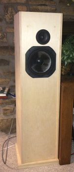
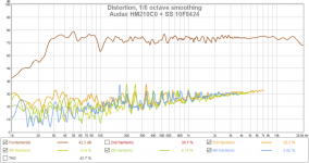
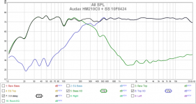
The cabinets are fresh out of glue-up. They still need to be routed around the edges and of course they will get a nice veneer finish. However, I wanted to confirm that the performance would match modeling. Here are some graphs:
First an iPhone pic of one of the cabinets. The first set of graphs are of one cabinet 0.5m on the tweeter axis. The second set of graphs are at the listening chair 2.5m back, the speakers 2.5m apart and square with the walls. Therefore, the microphone is 30* off axis and slightly above the tweeter.
All of this was quick-and-dirty. Took me ~1hr to run the tests. I still have to finish the cabinets, break in the drivers and play with the stuffing, so I expect the final results to be somewhat better. I will dial in the XO and EQ for the speakers at 0.5m with the PEQ of the individual channels, then when I get to my room in Dallas, I’ll EQ the room with the input PEQ.
I must say that my initial listening impression is positive. These speakers are very clean and crisp. Rock solid image and overall nice sound. One thing I will do in the final adjustments is not compensate for the 10F’s rising response on axis. That made the top end rather dull and lifeless. Yes, I could point the speakers at the listening chair, but that severely reduces the size of the sweet spot.
Bob
I have been playing with low XO 2-way systems (OK – FAST) for a couple of years now. All have been sat-sub system, but this one is all in one box. The bass cabinet is a standard MLTL loaded with the Audax HM210C0 and tuned to 32Hz. The mid-tweet is the Scan Speak 10F8424G0 is loaded into a piece of 4” PVC pipe. The pipe is open and stuffed. The XO is Harsch style at 300Hz implemented in a nanoDIGI.
The cabinets are fresh out of glue-up. They still need to be routed around the edges and of course they will get a nice veneer finish. However, I wanted to confirm that the performance would match modeling. Here are some graphs:
First an iPhone pic of one of the cabinets. The first set of graphs are of one cabinet 0.5m on the tweeter axis. The second set of graphs are at the listening chair 2.5m back, the speakers 2.5m apart and square with the walls. Therefore, the microphone is 30* off axis and slightly above the tweeter.
All of this was quick-and-dirty. Took me ~1hr to run the tests. I still have to finish the cabinets, break in the drivers and play with the stuffing, so I expect the final results to be somewhat better. I will dial in the XO and EQ for the speakers at 0.5m with the PEQ of the individual channels, then when I get to my room in Dallas, I’ll EQ the room with the input PEQ.
I must say that my initial listening impression is positive. These speakers are very clean and crisp. Rock solid image and overall nice sound. One thing I will do in the final adjustments is not compensate for the 10F’s rising response on axis. That made the top end rather dull and lifeless. Yes, I could point the speakers at the listening chair, but that severely reduces the size of the sweet spot.
Bob
Attachments
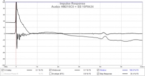
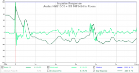
Very nice work! Must sound incredible - very clean low distortion system. Can you show us the IR/SR plot with more data to the left? The offset high plateau on the step response concerns me. I am not sure if you are time aligned with the leading edge of the woofer - looks like you are sitting at the top of the woofer step which actually looks like a smooth hill all by itself. This would indicate the delay might be too long on the 10F. It will sound good, but can sound even better. One way to tell is to look at the SR of the woofer and mid tweet by themselves and see where they align. That gives you better infra of roughly how much to delay. It probably sounds very good but tweaking the delay to get it perfect will make the percussion really snap. Drum rim shots and bongos are a good listening test.
It's a bit of work (but faster in long run than manually tweaking minidsp with mic) but I found the best way to make an accurate Harsch XO is to measure the raw responses of the drivers and combined in parallel without touching mic. Then exporting minimum phase frd files into either Bagby's PCD or Waslo's Xsim, overall the target reaponse of BW4 on woofer and Bessel 2 on mid/tweet and massaging the filter slopes and EQ's to get best fit. This also accounts for acoustic centers offset. Then transfer EQ and filter settings to minidsp or nanoDIGI. This will give textbook perfect Harsch XO with 55deg phase shift bump and flat phase otherwise.
Great work and good luck at the exhibition.
Last edited:
@xrk
Thanks for your input. Of course, tomorrow the speakers go back into the shop, the drivers into their boxes and the woodworking commences. I'll revisit your comments when I do the final alignment -- probably a month or so down the road.
As I said, this was a quick-and-dirty confirmation of the basic concept. I simply set the delay at 3ms, then ran a test at 2.7ms and 3.3ms. 3ms is close, but I didn't search for best.
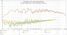
I think the key to getting the Harsch XO right is EQing the drivers as flat as is reasonable, particularly in the +/- octave around the XO. The suckout at 100Hz on the Audax is probably a room effect, but it needs to be pursued. Also, the small notch at 350Hz on the SS is right in the middle of the XO and it most likely an artifact of the TL. Once the driver responses are straightened out, the XO will fall into place. I did not show them, but the individual driver IR plots are rather nice all by themselves.
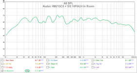
I am surprised that no one mentioned the in-room plots. I posted them just to show how a room screws up all of the good work at 0.5m. The microphone was not centered on the speakers, and the ceiling/floor bounce destroyed the IR plot
Bob
Thanks for your input. Of course, tomorrow the speakers go back into the shop, the drivers into their boxes and the woodworking commences. I'll revisit your comments when I do the final alignment -- probably a month or so down the road.
As I said, this was a quick-and-dirty confirmation of the basic concept. I simply set the delay at 3ms, then ran a test at 2.7ms and 3.3ms. 3ms is close, but I didn't search for best.
I think the key to getting the Harsch XO right is EQing the drivers as flat as is reasonable, particularly in the +/- octave around the XO. The suckout at 100Hz on the Audax is probably a room effect, but it needs to be pursued. Also, the small notch at 350Hz on the SS is right in the middle of the XO and it most likely an artifact of the TL. Once the driver responses are straightened out, the XO will fall into place. I did not show them, but the individual driver IR plots are rather nice all by themselves.
I am surprised that no one mentioned the in-room plots. I posted them just to show how a room screws up all of the good work at 0.5m. The microphone was not centered on the speakers, and the ceiling/floor bounce destroyed the IR plot
Bob
The in room result, is that with both speakers playing? Either that (and you weren't exactly equal distance to both speakers) or you have a mighty strong and very early reflection... and a couple of other early reflections at a more normal time interval (3 ms). The big peak before 0.5 ms must come from somewhere obvious...
That's pretty close and strong though.
That's pretty close and strong though.
I think the key to getting the Harsch XO right is EQing the drivers as flat as is reasonable, particularly in the +/- octave around the XO.
Yes, that is key - and to get it as flat as possible up to 2 octaves above and below XO point. That is not always possible but we do our best. On the woofer side not as critical as it is -24dB/oct falloff.
One trick I have recently learned from Wesayso is to use the "Frequency Dependent Window" (FDW) gating function in REW. It's in the latest version of REW in the "IR" button. Set it to 1/6th octave FDW and set no smoothing on graphs. This basically allows you to see the intrinsic shape of the response of the drivers (woofer and mid/tweet) without reflections or room effects. So what you EQ here will be something that is within control, as opposed to reflections, which you should not be EQ'ing the driver flat against prior to applying the XO filters. It will suggest smooth and broad PEQ's - typically no Q greater than 2, typically 1.2 to 1.5. The FDW is different than straight time gate as that won't tell you anything about your woofer's response.
I am sure you will get it all dialed in right later and it will knock people's socks off when they hear it.
Btw, a 300Hz Harsch XO suggests a 1.67ms delay on mid/tweet and assuming acoustic center of woofer is circa 1 inch behind 10F/8423 (or ~0.07 microseconds delay), suggests the delay should be in neighborhood of ~1.60 ms behind the woofer.
Nice speaker project, had distance not been so long would visit LSAF for that.
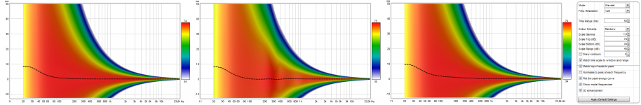
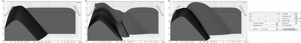
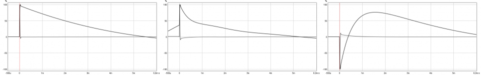
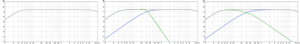
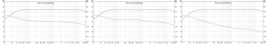
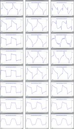
From all the tech talk and if can help down the road when back from shop here some visual data how it looks in perfect domain. Will guess you end up later a XO point little bit higher and ctc distance will probably support within 1/4 wave up in area between 400-500Hz. Common in plots is stopbands are set BW2 32Hz - BW2 18kHz, then three comparison in plots are first a perfect minimum phase fullranger or could be a multi-way with FIR correction measured on design axis, then HARSH XO at 300Hz, and last is LR2 XO at 300Hz where tweeter polarity is reversed.
If you like to play with target files attach the BW2 32Hz - BW4 300Hz / BS2 300Hz - BW2 18kHz band passes as IR-wav files to import into REW, and when imported command "Estimate IR Delay" to zero align IR for correct phase.
Those two can also be summed in "SPL" window commanding A+B where A is highlighted as LF part and B is highlighted as HF part, but before that HF part needs in "Impulse" window be set a -1,66mS delay. When A+B sum is generated it also need "Estimate IR Delay" command to show right system phase.
Attachments
Well, yeah.And you have to deal with the rooms at Lone Star
And so many don't. I hate the boom-tizz that a small concrete room causes. This is why I EQ the speakers in the output section of the nanoDIGI. That is where the XO is developed and reamains unchanged with venue. I EQ the room in the input section for different venues.
What causes the trouble in the 200-300 Hz range, do you think?
Part of it is characteristic of the Harsch XO, part due to the small dip in the SS FR.
Bob
The in room result, is that with both speakers playing? Either that (and you weren't exactly equal distance to both speakers) or you have a mighty strong and very early reflection... and a couple of other early reflections at a more normal time interval (3 ms). The big peak before 0.5 ms must come from somewhere obvious...
That's pretty close and strong though.
Right. Both speakers playing and slightly off center. That's the cause of the second main bang.
Bob
The in-room response is why I don't try so hard to make things perfect anymore.
Sort of agree with single driver speakers, but with a 2-way, if the XO isn't right, you don't have a chance.
Bob
Good work here. So good to see some actual measurements! I can "see" that this speaker will sound good.
You might try a slightly sloping in-room response. I would try either the B&K curve or a constant slope that is -6db at 10 kHz compared to 100 Hz. Below 80 Hz, my personal preference is for a 3-6 db boost up to 40 Hz and then let it fall off naturally. This sounds most pleasing to me.
You might try a slightly sloping in-room response. I would try either the B&K curve or a constant slope that is -6db at 10 kHz compared to 100 Hz. Below 80 Hz, my personal preference is for a 3-6 db boost up to 40 Hz and then let it fall off naturally. This sounds most pleasing to me.
You might try a slightly sloping in-room response. I would try either the B&K curve or a constant slope that is -6db at 10 kHz compared to 100 Hz. Below 80 Hz, my personal preference is for a 3-6 db boost up to 40 Hz and then let it fall off naturally. This sounds most pleasing to me.
Here's the deal. I'm a bit older than most posters here. My hearing starts to degrade ~8kHz and is gone by 12kHz. If I set the FR flat, it sounds dull to me. If I set it for a rising response, it will sound hot to the bat-eared. I'll get a consensus from visitors as to what sounds best to the masses.
Bass boost is tricky. A bit sounds nice and warm and fuzzy, but too much is bloat. But then it is near impossible to get a decent bass in a hotel room.
Bob
Yes, by all means compensate for hearing loss. In the hotel room, you could even have different settings for HF level -- could be done using the nanoDIGI you have. Might be pretty cool actually.
The B&K curve has typically sounded very neutral to me. Perfect amount of warmth/chestiness without sounding congested or muddy. Bass boost is again one's own preference. Too much is never good.
DSP opens up a whole new world.
The B&K curve has typically sounded very neutral to me. Perfect amount of warmth/chestiness without sounding congested or muddy. Bass boost is again one's own preference. Too much is never good.
DSP opens up a whole new world.
- Status
- This old topic is closed. If you want to reopen this topic, contact a moderator using the "Report Post" button.
- Home
- Loudspeakers
- Full Range
- What I am taking to LSAF