Thank you for a nice thread, xrk971. Looks very good!
The Fountek has a magnet larger than its frame, which should lend itself to mounting from the inside of the cabinet. Perhaps thickening the cabinet wall to 2.51 inches (63.75 mm) could be used to both achieve the Fountek mounting and implement the time delay.
The old speakers sold cheaply at many recycled-goods stores could be a convenient source of cabinets for those without power tools or access to wood cutting services.
jonathan
Last edited:
Use of PCD to assist XO and PEQ for Textbook BW1
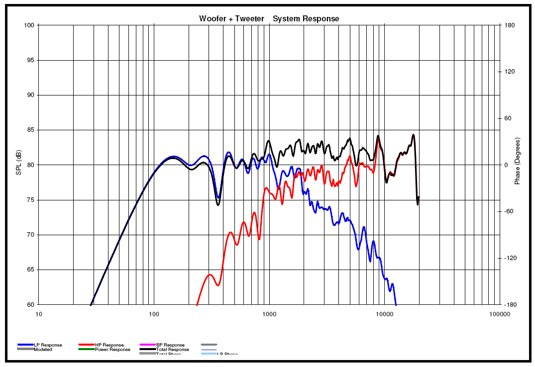
I used the PCD worksheets developed by Jeff Bagby for simulating the response and how to apply PEQ's to shape the response to match a textbook BW1 slope. I set the acoustical XO frequency at 1700Hz and applied various electrical XO frequencies and PEQ's. The method is very efficient and no trial and error. Collected raw responses from both drivers separately and combined in parallel running direct drive full range. The raw data allowed me to calculate the acoustic offset of the woofer is -2.54cm behind the tweeter.
Here are the results of the PCD worksheet, this is the predicted response using the raw frd files:
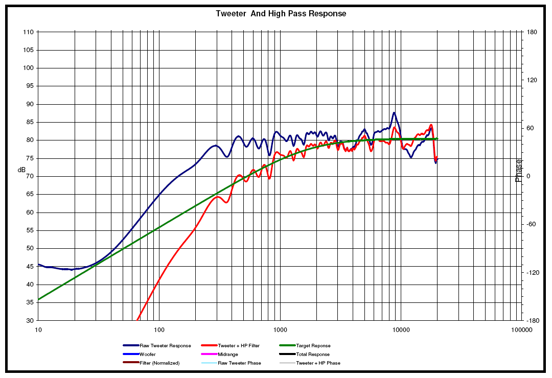
These are the simulated high pass and low pass functions with the electrical filter and PEQ's applied to get it to hit the BW1 target:
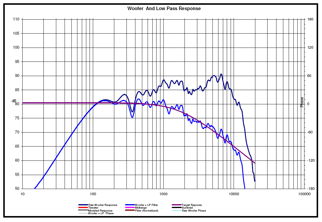
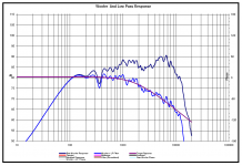
This is the simulated low pass function and trying to get it to hit the BW1 target:
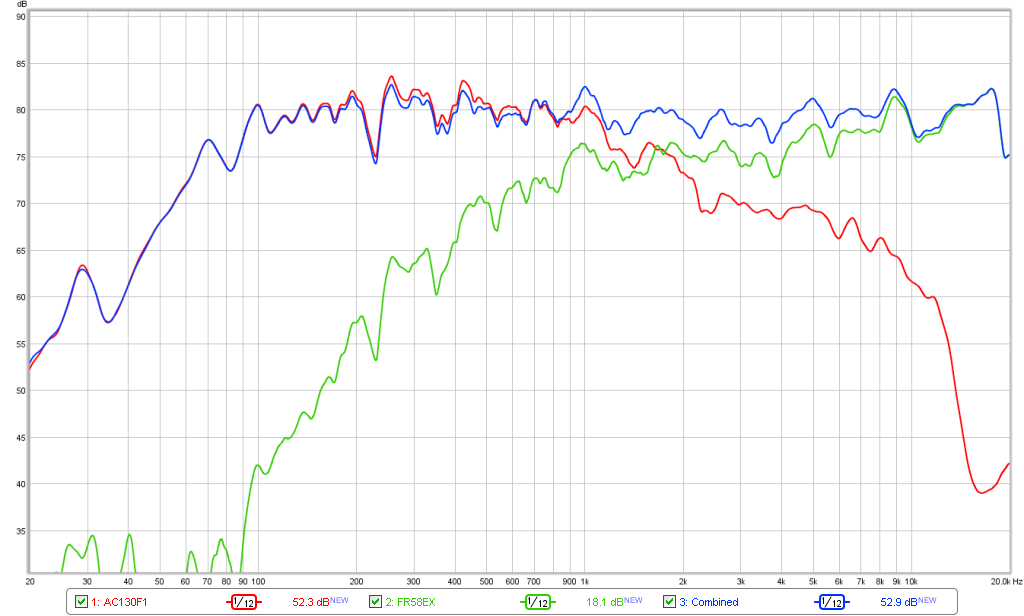
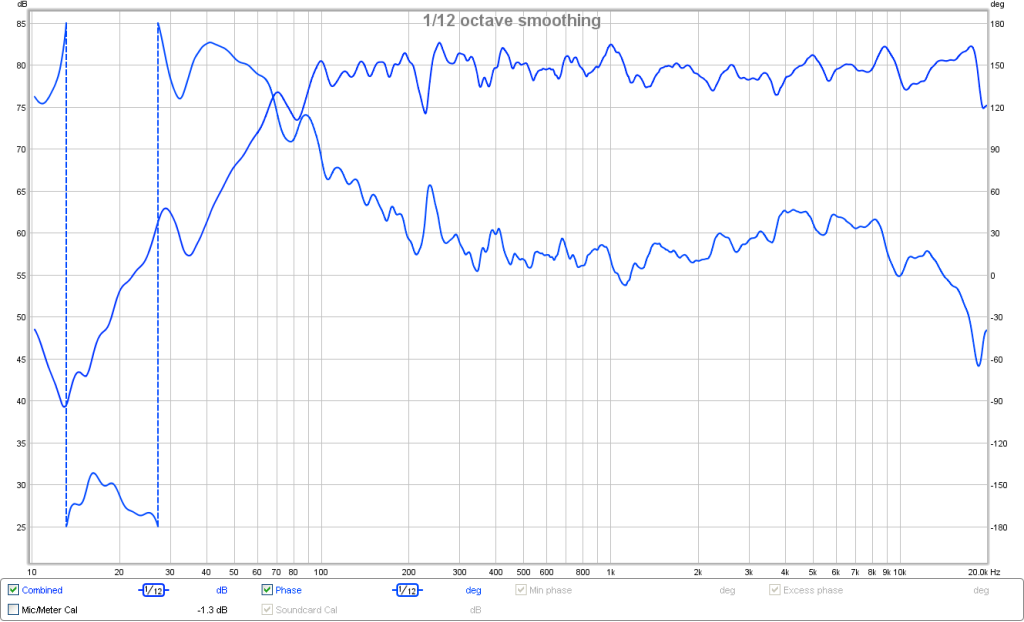
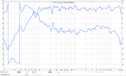
Here are the measured results of the XO as implemented according to the simulation:
Measured phase:
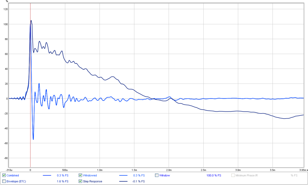
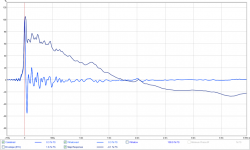
Measured impulse and step response:
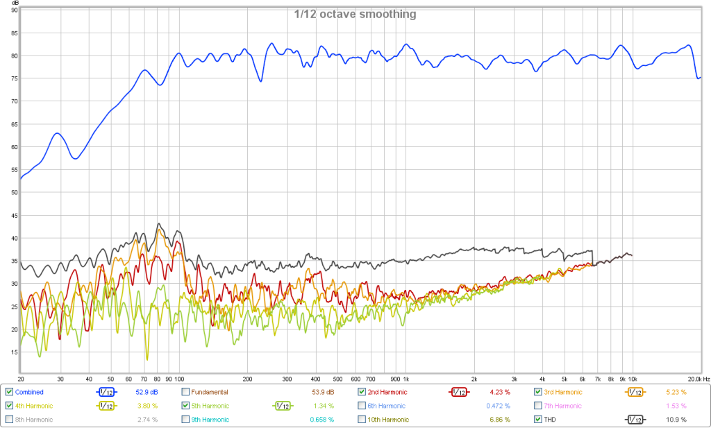
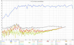
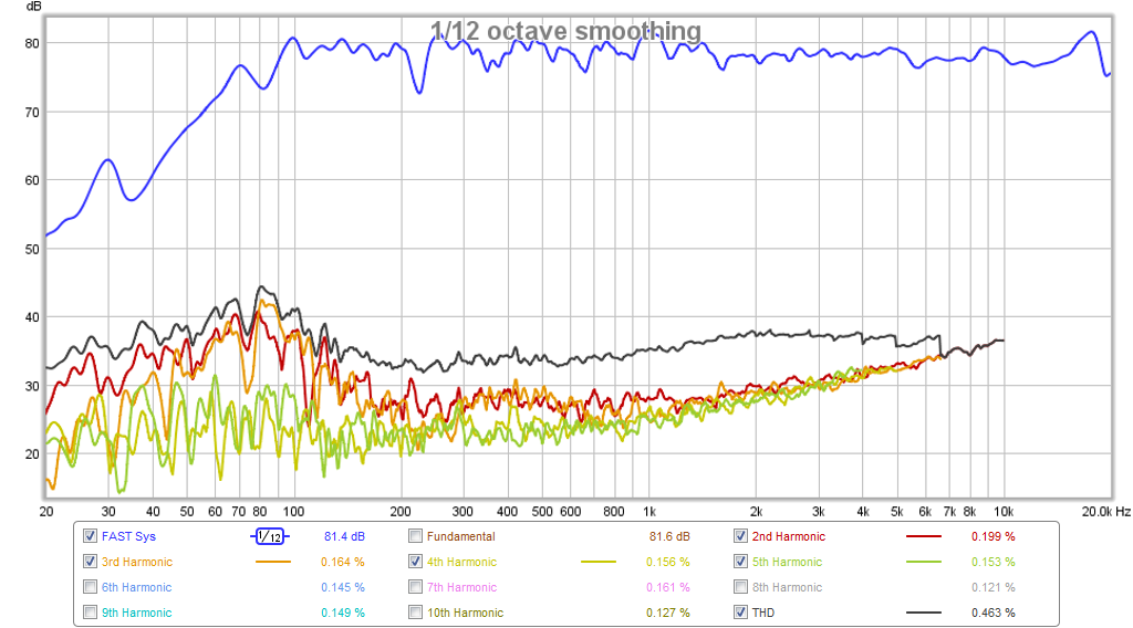
and harmonic distortion:
One good thing is that this was achieved on the first try with no trial and error in front of miniDSP. A good starting point or manual tweaks, which can get it better as my phase and IR/SR from last night appears to be better.
I used the PCD worksheets developed by Jeff Bagby for simulating the response and how to apply PEQ's to shape the response to match a textbook BW1 slope. I set the acoustical XO frequency at 1700Hz and applied various electrical XO frequencies and PEQ's. The method is very efficient and no trial and error. Collected raw responses from both drivers separately and combined in parallel running direct drive full range. The raw data allowed me to calculate the acoustic offset of the woofer is -2.54cm behind the tweeter.
Here are the results of the PCD worksheet, this is the predicted response using the raw frd files:
These are the simulated high pass and low pass functions with the electrical filter and PEQ's applied to get it to hit the BW1 target:
This is the simulated low pass function and trying to get it to hit the BW1 target:
Here are the measured results of the XO as implemented according to the simulation:
Measured phase:
Measured impulse and step response:
and harmonic distortion:
One good thing is that this was achieved on the first try with no trial and error in front of miniDSP. A good starting point or manual tweaks, which can get it better as my phase and IR/SR from last night appears to be better.
Attachments
-
 fr58ex-ac130f1-fast-pcd-assist-summed-response.PNG90.1 KB · Views: 872
 -
 fr58ex-ac130f1-fast-pcd-assist-hd.png155.2 KB · Views: 837
 -
 fr58ex-ac130f1-fast-pcd-assist-ir-sr.png60.1 KB · Views: 1,839
 -
 fr58ex-ac130f1-fast-pcd-assist-phase.png79 KB · Views: 867
 -
 fr58ex-ac130f1-fast-pcd-assist-xo.png80.9 KB · Views: 1,915
 -
 fr58ex-ac130f1-fast-pcd-assist-low-pass-filter.PNG88.4 KB · Views: 1,254
 -
 fr58ex-ac130f1-fast-pcd-assist-high-pass-filter.PNG88.7 KB · Views: 868
Last edited:
X
Where did all the new distortion come from?
Jay
I don't see any thing more than what was already there in Post #1:
Compare this to above post - about -40dB in general and a rise to a broad hump of -30dB around 80Hz.
Here is new HD plot from above post:
x
I agree looking at the plots, the traces look the same. At the bottom of the plots, there is information regarding the percentage distortion for the various harmonics. In the lower right hand corner is percentage THD. In the plot from your first post, the THD is .463% while the THD from post #22 10.9%. I'm sure I've missed something important. Id like to find out.
Jay
x
I agree looking at the plots, the traces look the same. At the bottom of the plots, there is information regarding the percentage distortion for the various harmonics. In the lower right hand corner is percentage THD. In the plot from your first post, the THD is .463% while the THD from post #22 10.9%. I'm sure I've missed something important. Id like to find out.
Jay
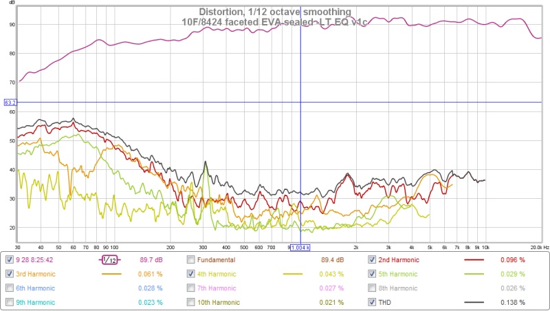
Oh the numbers on the bottom are for a cursor location at a particular frequency. If we accidentally move the cursor it will show very different numbers. By default the cursor is not displayed in the image. I try to remember to place it at 1khz and to click the "show cursor" button. If you can not see the cursor, then just ignore those numbers. Probably cursor was moved over to the 80hz area in X's second image.
You can see the cursor in this image from one of my recent uploads in another thread. All the numbers at the bottom correspond to the distortions at the 1.004khz point.
Last edited:
Sorry, those numbers represent wherever the cursor is set at - I did not pay attention to where it was positioned. Usually people like to report the 1kHz value for THD, and another is the bottom frequency bandwidth point, in this case 100Hz.
From post #1: 0.47% THD at 1kHz, 0.83% THD at 100Hz
From post #22: 0.38% THD at 1kHz, 0.87% THD at 100Hz
So basically the same...
From post #1: 0.47% THD at 1kHz, 0.83% THD at 100Hz
From post #22: 0.38% THD at 1kHz, 0.87% THD at 100Hz
So basically the same...
Diffraction Control - Think Rectangles not Circles!
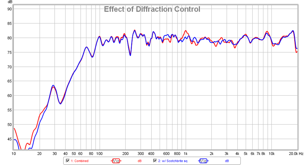
After Jeshi posted the nice closeup photo of the diffraction control felt/foam strips used on LS3/5A it reminded me that the worst diffraction I ever measured was a round baffle. I had a nice round cutout through the Scotchbrite and that was probably not ideal I thought to myself.
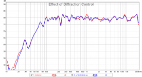
So I went in and cut out a rectangle and added some extra tall strips on the horizontal axis only to introduce asymmetry - a rectangle is better than a square. A square is better than round. But a trapezoid is even better than a rectangle (Hence all of Jeshi's baffles are trapezoids).
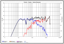
It was fortunate that the mic and speaker were left exactly in the same spot and the only change was the shape of the scouring pad. The results are quite amazing - a smoother response through the critical 500Hz to 4kHz range and peaks higher up have the "bite" taken out of them. I think that this is a significant improvement and costs essentially nothing - there is a reason 100,000 units of LS3/5A's have this - it works! I know Dunlavy speakers also have it around the dome tweeter. So here is quantitative proof it works.
After Jeshi posted the nice closeup photo of the diffraction control felt/foam strips used on LS3/5A it reminded me that the worst diffraction I ever measured was a round baffle. I had a nice round cutout through the Scotchbrite and that was probably not ideal I thought to myself.
So I went in and cut out a rectangle and added some extra tall strips on the horizontal axis only to introduce asymmetry - a rectangle is better than a square. A square is better than round. But a trapezoid is even better than a rectangle (Hence all of Jeshi's baffles are trapezoids).
It was fortunate that the mic and speaker were left exactly in the same spot and the only change was the shape of the scouring pad. The results are quite amazing - a smoother response through the critical 500Hz to 4kHz range and peaks higher up have the "bite" taken out of them. I think that this is a significant improvement and costs essentially nothing - there is a reason 100,000 units of LS3/5A's have this - it works! I know Dunlavy speakers also have it around the dome tweeter. So here is quantitative proof it works.
Attachments
Last edited:
I remember the first time I saw an LS3/5a in person with this dodgy square foam around the tweeter and thought "wow that is a total hack, I can't believe these are so well respected". (ok I was young). I even remember asking the shop guy "why didn't they remove that packing foam?", and "really that is how it is designed to be?!?"
But now after all these years, I realize that proper audio design really is a huge compromise and that the best design approach may not yield the most pretty looking speaker. And the opposite too (that most of these pretty looking speakers on the market might not be the most optimal of designs). I still find it hard to imagine using a speaker with exposed brillo-pads / foam standing up off the baffle, but I am trying to get used to it.
If anyone is curious, here is the software I use for simulating baffle diffraction and why I ended up using trapezoids on so many of my speakers
Baffle Diffraction Simulator
and excellent data X showing that this diffraction control foam/felt/scotchbrite actually works
Last edited:
I still find it hard to imagine using a speaker with exposed brillo-pads / foam standing up off the baffle, but I am trying to get used to it.
Yes, pretty low WAF (or BAF as in your case).
") But think of it this way, if you have a spill that needs cleanup, it comes right off (held in place with velcro) and can do double duty as a sponge and diffraction control. If I can modify the cloth grill to fit the new driver that would help some, but the grill frame probably adds its own problems.
But think of it this way, if you have a spill that needs cleanup, it comes right off (held in place with velcro) and can do double duty as a sponge and diffraction control. If I can modify the cloth grill to fit the new driver that would help some, but the grill frame probably adds its own problems.I also use felt around my tweeters, inspired by the LS3/5a. I cant say ive used brillo pads, normally I use 1/2" square woolen felt. Ive been meaning to try those 'magic eraser' sponges (IIRC Melamine foam which if I'm correct, is also very good)
I found that by listening, the impact is greater than a baffle edge roundover, which is the normal recommendation here.
Double benefit is that its easily adjustable for optimum results, and the side effect of a small measure of directivity control, another welcome bonus (especially when using non waveguide loaded dome tweeters.
Last edited:
Got Square Waves?
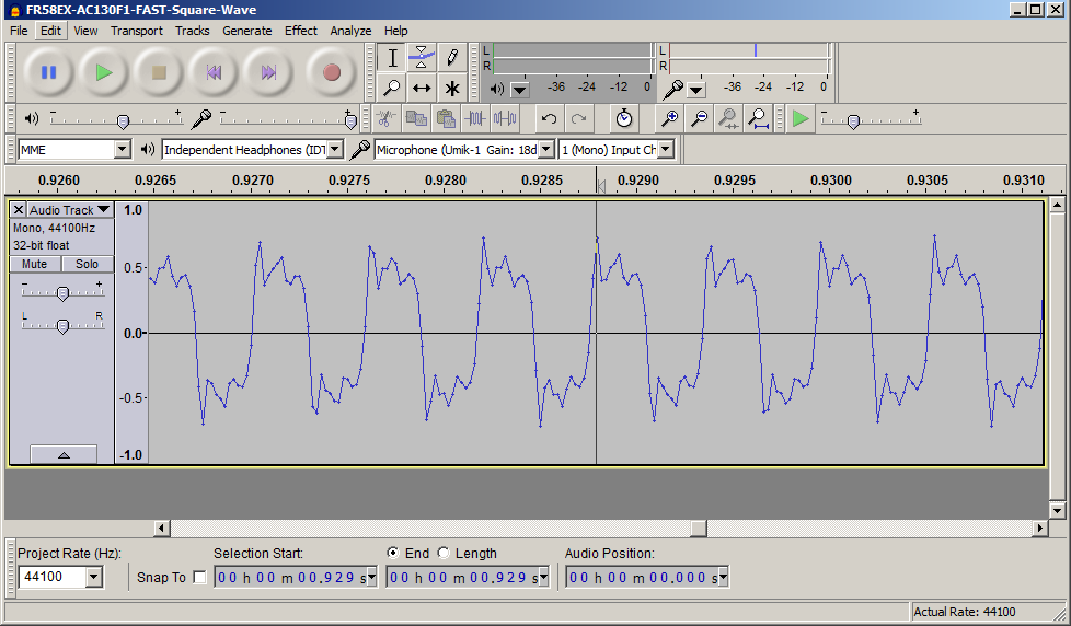
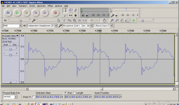
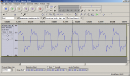
For grins, I recorded some square waves using the UMIK-1 and Audacity with REW's function generator. It's not perfect, but you can see the resemblance to a square wave at both 500Hz and at the XO frequency of 1.7kHz (where both drivers have to be in perfect unison) for it to work.
At 500Hz:
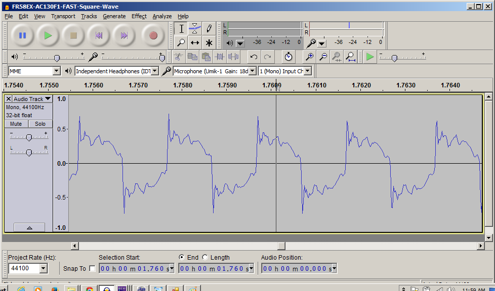
At 1.7kHz:
For grins, I recorded some square waves using the UMIK-1 and Audacity with REW's function generator. It's not perfect, but you can see the resemblance to a square wave at both 500Hz and at the XO frequency of 1.7kHz (where both drivers have to be in perfect unison) for it to work.
At 500Hz:
At 1.7kHz:
Attachments
Thanks sharing experience "Diffraction Control - Think Rectangles not Circles" that's really nice data before and after and pretty cheap : ) it will never work on a B&W speaker for many reasons .
Now take that tech a step further and 3d print some special formed models and if it covers drivers a bit or more doesn't matter if it improves performance, little as you talked about over at onni's thread to stuff into waveguide.
Those square waves is pretty nice especially the 500Hz has perfect fast vertical transient attack and decay.
Got fresh made batch of fibre glass cone woofers today when they settled to indoor temp will share DATS sweep and pictures over at jeshi's thread.
.Now take that tech a step further and 3d print some special formed models and if it covers drivers a bit or more doesn't matter if it improves performance, little as you talked about over at onni's thread to stuff into waveguide.
Those square waves is pretty nice especially the 500Hz has perfect fast vertical transient attack and decay.
Got fresh made batch of fibre glass cone woofers today when they settled to indoor temp will share DATS sweep and pictures over at jeshi's thread.
But a good wood box is always the stumbling point for me given no tools or wood shop.
Same here. How then, though, did you rebate the woofers, what with their somewhat unusual outline?
Same here. How then, though, did you rebate the woofers, what with their somewhat unusual outline?
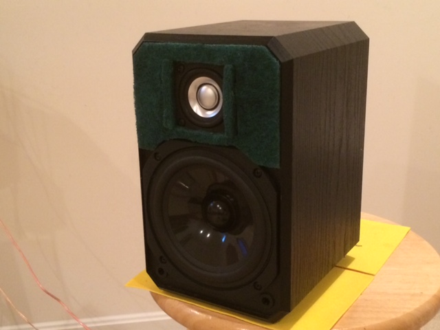
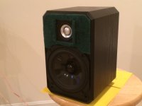
If you look carefully, I did not rebate the woofers, they sit surface mounted with a thick bezel. Hopefully, at the lower woofer frequencies, diffraction off the bezel is not an issue. I did add foam core around the tweeter to make it as flush as possible and added the brillo anti diffraction treatment.
The rebate shown in post one where the driver is not in place is the factory woofer rebate for a pincushion shaped frame. The new driver is slightly larger and covers the old rebate. If I were to buy a Dayton, Classic woofer DC130A, I am told it has the same exact profile as the stock woofer and would be a drop in replacement, shape-wise.
http://www.parts-express.com/dayton-audio-dc130a-8-5-1-4-classic-woofer-speaker--295-303
Last edited:
It appears that these speakers are flat down to about 90 hz.
What was done to compensate for baffle step loss, if anything?
would it not have been better to chose a fullranger with 89 db efficiency
for the top so as to not throw away alot of power? I see that the AC130
F are 89 db.
I am missing something here.
What was done to compensate for baffle step loss, if anything?
would it not have been better to chose a fullranger with 89 db efficiency
for the top so as to not throw away alot of power? I see that the AC130
F are 89 db.
I am missing something here.
- Status
- This old topic is closed. If you want to reopen this topic, contact a moderator using the "Report Post" button.
- Home
- Loudspeakers
- Full Range
- FR58EX and AC130F1 micro-FAST / WAW