Jeshi how effective do you think a sheet of eva would be between two drivers in a bipole design vs say just a thick wad of pillow stuffing (what I currently have in place)?
Are the two drivers attached to each other by the back side, or are they supported on each end by a front baffle? I would imagine that pillow stuffing has no structural support and is just acting as internal sound dampening.
If you want to physically have the dipole drivers touching each other and want a material to absorb vibration but also provide support then EVA is maybe the best. If you just want a dampening material, then maybe neoprene foam would be just as good. But neoprene foam is floppy and can not provide any structural shape.
If you want a sound absorbing layer to isolate the two dipole speakers from each other, then yes I think EVA (even the cheap floor panel type) would work nicely. You can pick up the cheap floor panel EVA at almost any store from Walmart to Target to HomeDepot type places (not sure what the Australian equivalent is), probably for $7-10 a pack. If you also find some neoprene, maybe from a well stocked fabric store, then a sandwich of EVA/neoprene/EVA would make an excellent sound isolation layer. Maybe like this from amazon.com.au 4 Tiles EVA Fitness Home Yoga Gym Interlocking Rubber Floor Puzzle Mat for Protection Portable Durable Lightweight- Black: Amazon.com.au: Sports, Fitness & Outdoors
The EVA seems to work best when used as structural material (front baffle for mounting drivers, enclosure walls, open baffle side panels) where the material will need to absorb vibrations and/or provide sound absorption (like front baffle reflection absorption)
Last edited:
Hi Jeshi,
They're currently mounted in a polystyrene foam box, initial results have been promising. I'm thinking of mechanically coupling them together with some wooden rod but with the eva between them as a way to clean up the sound but my concern was that the eva would be an inferior absorber of high frequencies vs traditional stuffing. I'm not looking to use eva for structural reinforcement just as an absorber.
They're currently mounted in a polystyrene foam box, initial results have been promising. I'm thinking of mechanically coupling them together with some wooden rod but with the eva between them as a way to clean up the sound but my concern was that the eva would be an inferior absorber of high frequencies vs traditional stuffing. I'm not looking to use eva for structural reinforcement just as an absorber.
Hi Jeshi,
They're currently mounted in a polystyrene foam box, initial results have been promising. I'm thinking of mechanically coupling them together with some wooden rod but with the eva between them as a way to clean up the sound but my concern was that the eva would be an inferior absorber of high frequencies vs traditional stuffing. I'm not looking to use eva for structural reinforcement just as an absorber.
Well have a look at some of the tests I did like some Panel resonance tests: here
Panel transmission tests: here
I think EVA absorbs sound (sound barrier, panel leakage) as good or better than neoprene especially in high frequencies. And I think neoprene is considered similar to felt for lining the walls of speakers for sound absorption. Look at the 10mmEVA+4mm neoprene, it has a -35db suppression of transmitted frequencies from 7khz and up. Even a simple 10mm EVA alone give -25db to -30db suppresion from 7khz up
I think for your application, you don't need the high-spec EVA that Mattes and I are using for structural support, so you can try the cheaper lower density EVA floor panel foam like I linked for $20au. It is cheap enough that it might be worth trying to experiment with it.
Last edited:
Thanks for your input jeshi.
I have another question, this may be already answered in this thread? How porous is EVA? Does it have the same effect as polyester stuffing in an enclosure of increasing the perceived internal volume from the drivers point of view?
No it's the opposite, it will decrease the internal volume. It's a closed cell foam so non-porous and it will decrease the internal volume in the same way as adding MDF supports would. It is also water proof and air tight, so nothing physical gets through. You can think of the EVA foam like a foam version of MDF+bitumen+felt (the sound transmission blocking of MDF, the vibration dampening of bitumen, and the sound reflection/absorption of felt) with different efficiencies/characteristics at these measures. MDF is good at blocking sound (prevent leakage) but resonates and is reflective. Bitumen is good for vibration dampening but floppy so so can't be used as support and is also highly reflective. Felt is floppy and not good at vibration dampening, but excellent at absorbing sound reflections. So EVA is like combining the best of the MDF+bitumen+felt sandwich with a single material. But I still stuff my EVA sealed speaker enclosures with fill (usually I use a loose wool). But for open baffles, I can use the raw EVA and not need to do anything else.
If you want to create an isolation wall between your dipole drivers (what would normally be an MDF panel, covered in bitumen and felt) to create two sealed boxes, then I would say EVA could be a great replacement with better vibration dampening than the MDF+bitumen+felt. But for a poly-fill replacement, then I would say no, don't bother with the EVA. But if you said you wanted to use wood to internally support the drivers. That would be an excellent use for EVA (not wood) since it would provide support and excellent vibration dampening (better than wood)
If you ever had flipflop sandals or Crocs then you have probably seen EVA foam.
cheers
jeshi
Last edited:
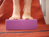
Maybe this will help explain what EVA foam is. It is a strong foam. Here is a picture of my 70kg/m3 EVA yoga block supporting my 80+kg weight with minimal compression. The foam that I use for speakers is 110kg/m3 density so even stronger. But EVA is also used as a building material under floors for vibration dampening, in gyms as floor mats, under machines for vibration dampening, and within walls for sound isolation (covering whole internal space so no leakage around edges). So it was this combination of strength, vibration dampening, and sound isolation (absorption) which made me explore this (and fall in love with it) as a speaker enclosure/front-baffle material.
Attachments
Last edited:
I live in Australia Jeshi, flip flops are a way of life over here
Thanks for the excellent explanation.
you are very welcome.
")
ps: small correction, closed cell foam is porous. For some reason I thought porous meant that the cells are connected and air/water can get through. But I double checked the definition and it simply means a material with pores or cells filled with liquid or gas.
Last edited:
Hi Jeshi,
I don´t have any leftovers, used up all the material, as I had to rework one of the small flowers due to a little bit too enthusastic sanding... that used up exactly all spare material.
Hi Ewollowe,
I´m not sure I understand your concept. You´re talking about Bipole, or Dipole? Could you maybe post a sketch or photo of your arrangement?
Hi XRK,
yes, it´s expensive, but has different properties as BB ply. For a short moment, I thought about building the bass flowers from wood, due to the price of EVA. But imaginating the handling of a baffle of 930 mm diametre and maximum of 160 mm depth made from wood, together with the 18 kg of the AE Dipole 18, let me quickly alter the direction of thoughts.
All the best
Mattes
Hi Mattes,
It's just a VERY basic bipole, driver on front, driver on back. I'll post some pics when I've made a little more progress as I've pulled them apart at the moment.
I'm one of those people crippled by analysis paralysis so inspired by all the foam antics going on here I bit the bullet and glue gunned a couple of cheap 8" fullrangers into a standard polystyrene box. Lots of issues but also lots of promise.
Hi everyone
As I am starting to plan my version of Mattes flower baffle, I decided to pick up some more small drivers (830983 and TA6FC00-04) for experimentation.
I want to duplicate the baffle diffraction test of linkwitz where he tries to induce a diffraction effect
Diffraction from baffle edges so that I can get some practical and empirical data to help in designing my flower baffle. For my first experiment, I decided to make 20cm round disks. A round baffle should create a dramatic baffle diffraction effect at a single frequency. By linkwitz calculations for a 0.2m diameter disk (Frequently Asked Questions) I should have a rise at 1700 and dip at 3400hz, but my measurements give me a consistent 1250hz rise and 2500hz dip from my round disk baffle. It's consistent so for now I will just accept it, but it would be good to figure out what is different or wrong with the calculation.
I am planning to do other diameter disks next. The idea is to see if I can actually create a tuned flower baffle to the driver (to create designed dips rises to the baffle effect).
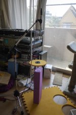
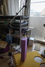
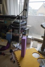
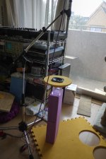
So here are some pictures of my test setup. A bit different to Linkwitz's but the idea is the same. (please forgive the messy background)


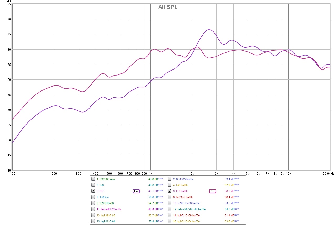
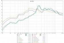
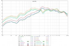
And here are some graphs
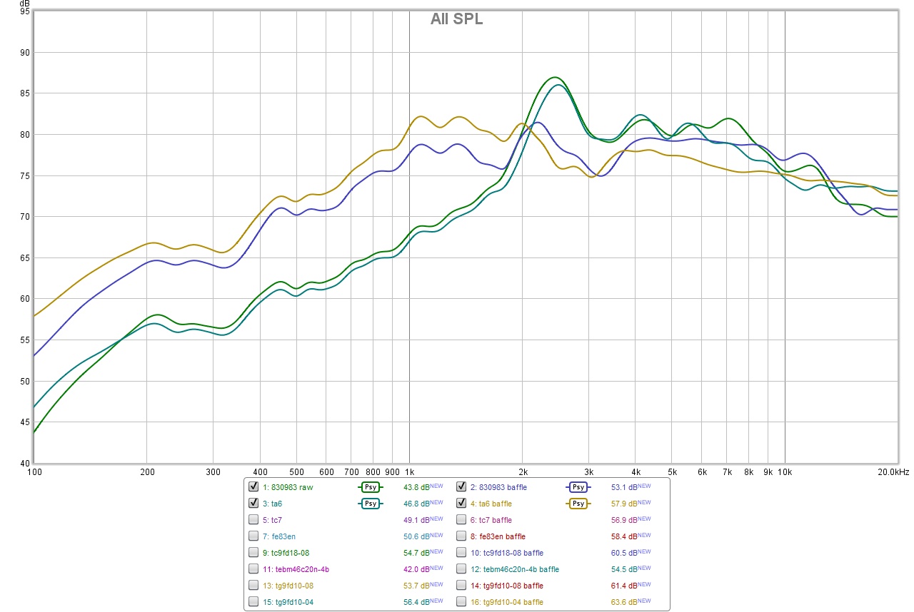
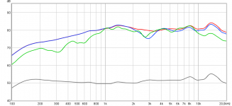
First my two new 2" drivers the 830983 and TA6FC00-04 both bare and with the 20cm disc baffle. These drivers have a natural peak at 2500hz so this seems to compensate with the baffle diffraction effect.
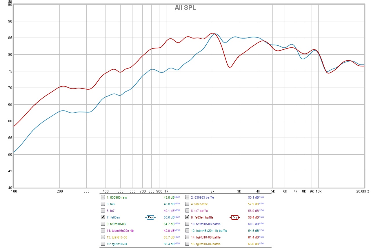
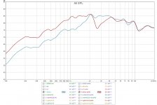
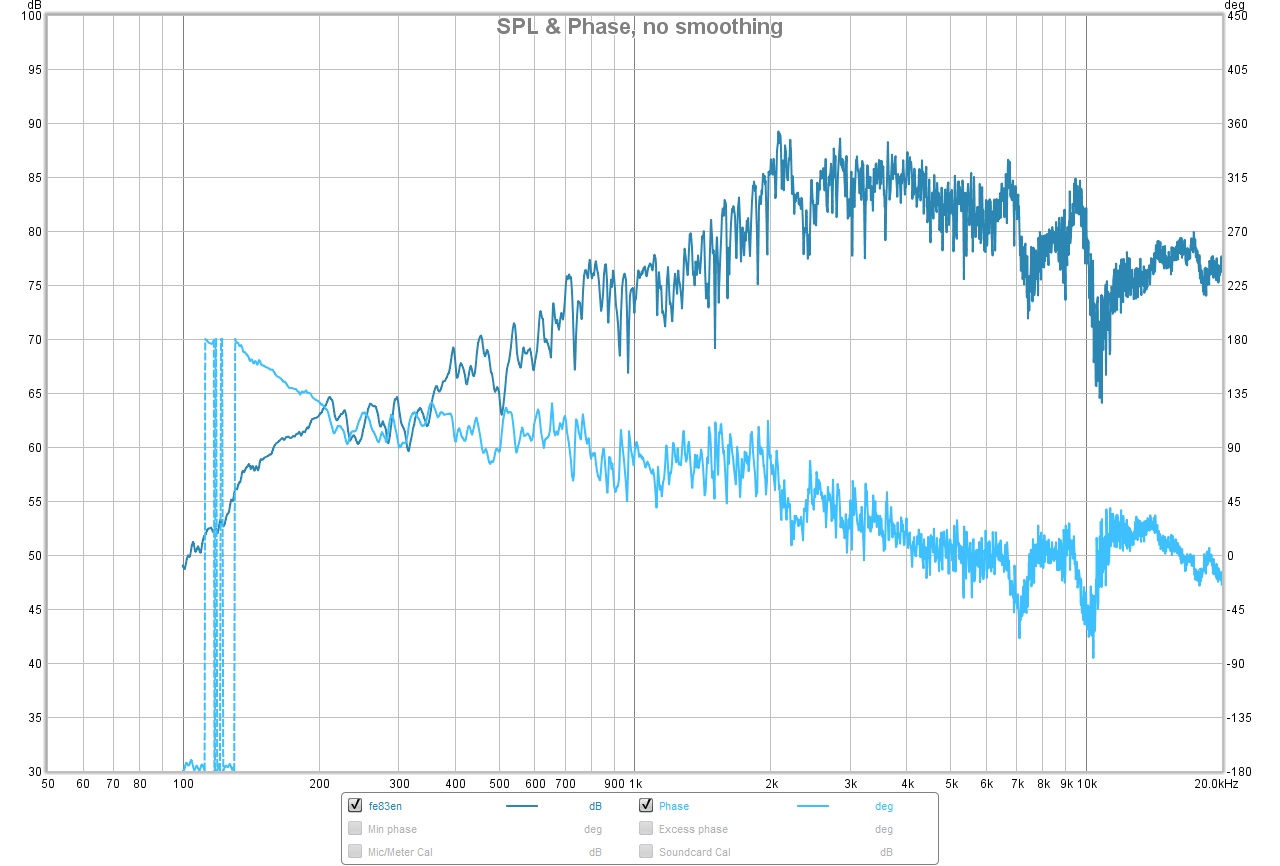
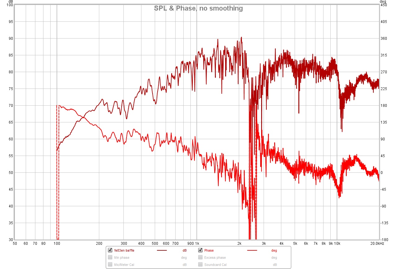
Next is the fostex FE83en. This has a quite flat response but that also means the round disk baffle creates a dramatic baffle diffraction dip effect
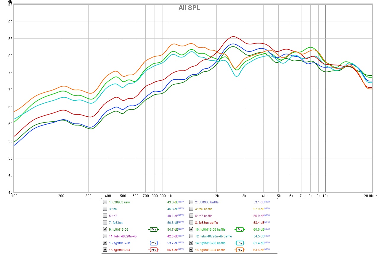
Next are the TC9FD18-08, TG9FD10-08 and TG9FD10-04. They have a small rise at 2500hz but it doesn't perfect compensate for the 2500hz baffle diffraction. So we get a noticeable dip at 2500hz.
And last is a TC7FD00-04. Bare this has a dramatic rise and actually doesn't sound that good, but placed on this 20cm round baffle and it is an almost perfect synergy and sounds really good. I probably won't use this for the final speaker, but it really opened my eyes to the possibility of using baffle shape to tune a driver to sound better.
again my motivation here was to duplicate the Linkwitz experiment to help me get some data for designing a flower baffle. These are not final designs, just some experimental data points.
cheers jeshi
As I am starting to plan my version of Mattes flower baffle, I decided to pick up some more small drivers (830983 and TA6FC00-04) for experimentation.
I want to duplicate the baffle diffraction test of linkwitz where he tries to induce a diffraction effect
Diffraction from baffle edges so that I can get some practical and empirical data to help in designing my flower baffle. For my first experiment, I decided to make 20cm round disks. A round baffle should create a dramatic baffle diffraction effect at a single frequency. By linkwitz calculations for a 0.2m diameter disk (Frequently Asked Questions) I should have a rise at 1700 and dip at 3400hz, but my measurements give me a consistent 1250hz rise and 2500hz dip from my round disk baffle. It's consistent so for now I will just accept it, but it would be good to figure out what is different or wrong with the calculation.
I am planning to do other diameter disks next. The idea is to see if I can actually create a tuned flower baffle to the driver (to create designed dips rises to the baffle effect).
So here are some pictures of my test setup. A bit different to Linkwitz's but the idea is the same. (please forgive the messy background)
And here are some graphs
First my two new 2" drivers the 830983 and TA6FC00-04 both bare and with the 20cm disc baffle. These drivers have a natural peak at 2500hz so this seems to compensate with the baffle diffraction effect.
Next is the fostex FE83en. This has a quite flat response but that also means the round disk baffle creates a dramatic baffle diffraction dip effect
Next are the TC9FD18-08, TG9FD10-08 and TG9FD10-04. They have a small rise at 2500hz but it doesn't perfect compensate for the 2500hz baffle diffraction. So we get a noticeable dip at 2500hz.
And last is a TC7FD00-04. Bare this has a dramatic rise and actually doesn't sound that good, but placed on this 20cm round baffle and it is an almost perfect synergy and sounds really good. I probably won't use this for the final speaker, but it really opened my eyes to the possibility of using baffle shape to tune a driver to sound better.
again my motivation here was to duplicate the Linkwitz experiment to help me get some data for designing a flower baffle. These are not final designs, just some experimental data points.
cheers jeshi
Attachments
-
 baffle-disk830983.jpg181.9 KB · Views: 685
 -
 baffle-disk-fe83en.jpg157.5 KB · Views: 679
 -
 baffle-disk-tc7.jpg156.4 KB · Views: 673
 -
 baffle-disk-tc9-tg9.jpg200.9 KB · Views: 681
 -
 P1130215-4.jpg270.2 KB · Views: 82
 -
 P1130214-3.jpg258.4 KB · Views: 78
 -
 P1130213-2.jpg273.6 KB · Views: 679
 -
 P1130211-1.jpg266.4 KB · Views: 663
Last edited:
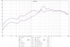
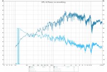
Here are two more graphs. This the the Fostex fe83en without any smoothing applied.
First is the bare driver which in this test setup actually gives a quite clean measurement
and then with the round 20cm baffle disk to create a single frequency dramatic baffle diffraction effect at around 2500hz
First is the bare driver which in this test setup actually gives a quite clean measurement
and then with the round 20cm baffle disk to create a single frequency dramatic baffle diffraction effect at around 2500hz
Attachments
Last edited:
...I should have a rise at 1700 and dip at 3400hz, but my measurements give me a consistent 1250hz rise and 2500hz dip from my round disk baffle. It's consistent so for now I will just accept it, but it would be good to figure out what is different or wrong with the calculation...
With static on axis position of microphone looks reason is the dynamic distance that change numbers, below models is examples of 0,1/0,2/0,4/0,8/1,6/3,2 meter distances.
Attachments
With static on axis position of microphone looks reason is the dynamic distance that change numbers, below models is examples of 0,1/0,2/0,4/0,8/1,6/3,2 meter distances.
thanks byrtt. I measured at 0.3meter distance on axis so that looks right. I've never used Edge, I used a different tool before. I will have a look at Edge again. But I also like doing empirical testing since it makes it more real for me.
thanks byrtt. I measured at 0.3meter distance on axis so that looks right. I've never used Edge, I used a different tool before. I will have a look at Edge again. But I also like doing empirical testing since it makes it more real for me.
Sorry i had one fault into that Edge model in i forgot tick on OB : )
In general imagine one thing that is important from ground up for defraction is to have a unit with as less as possible defraction from start on because at various other distances and angles to spot in space be it our ears or be it room reflections will force new dynamic frq responses to sum up and using EQ reverse corection will only work in one spot in space, so therefor think Mattes is on track using roundovers whereever he can get away with it.
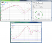
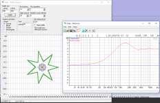
In spirit of model roundovers we can not use Edge so i tryed fire up free VituixCAD program which is new tool to me but have so much practical power and tools for speaker building. In below visual i traced your TC9 (green trace) sitting on the 200mm disc and used ZAPH audio graph (black trace) for TC9 response as reference for model, with microphone distance at 0,3m (thanks post that number) VituixCAD then output the blue trace and its not far from yours, the interesting smoother curve relative to green and blue is the red trace where round over is set to 30mm.
Second attachment below is sceendump from VituixCAD because heck it is interesting powerfull tool in it even could create vertical and horizontal directivity curves based on piston size from that diffraction tool process : ) also if we follow kimmsto guide into this post 679 (LINK: https://www.diyaudio.com/forums/software-tools/307910-vituixcad-68.html#post5584200) it can translate to IR file from simple txt/frd curves.
Attachments
In general imagine one thing that is important from ground up for defraction is to have a unit with as less as possible defraction from start on because at various other distances and angles to spot in space be it our ears or be it room reflections will force new dynamic frq responses to sum up and using EQ reverse corection will only work in one spot in space, so therefor think Mattes is on track using roundovers whereever he can get away with it.
In spirit of model roundovers we can not use Edge so i tryed fire up free VituixCAD program which is new tool to me but have so much practical power and tools for speaker building. In below visual i traced your TC9 (green trace) sitting on the 200mm disc and used ZAPH audio graph (black trace) for TC9 response as reference for model, with microphone distance at 0,3m (thanks post that number) VituixCAD then output the blue trace and its not far from yours, the interesting smoother curve relative to green and blue is the red trace where round over is set to 30mm.
I absolutely agree that Mattes is on the right track and his approach has inspired me to try a baffle approach. I definitely will eventually do a round over like Mattes, but I want to approach this as a learning exercise where I start with obviously bad baffles (round flat disk with sharp edges) and slowly approach Mattes flower and learn along the way. I thought this might be more fun than just copy his design, and this might allow me to gain additional insights to share with everyone.
In my previous speaker projects, I have used DSP to compensate for OB effects and although some speakers worked out great for my nearfield applications (where I basically sit in one location), I am realizing DSP-EQ is like you say "EQ reverse correction will only work in one spot in space" and thus is maybe not the best universal approach.
About the flat Zaph TC9 curve. Is this on a large "infinite" baffle to give the response without baffle edge effects?
VituixCAD looks great but I'm not sure I have the patience right now to learn that, but I will put on my todo list. thanks again for helping with this.
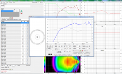
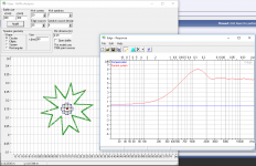
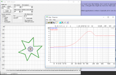
I was playing with Edge and tried a 7pointed star and modified 5/10point and 3/6point stars and they all worked out very nice. It still has the bump up but there is minimal ringing or dip down. Outer diameter is 300mm and inner diameter is maybe around 150mm but I modified the points by hand so I don't really know. I might try something like this next in my experiments.
Attachments
Last edited:
Nice work Jeshi! Thanks for taking us along on a learning journey. Glad you put that TC9FD18-8 to use right away. And thanks Byrtt for sharing with us all the tools to simulate these effects.
I have seen a similar first rise overshoot like that due to a different effect in a FLH. A tractrix on a Visaton FRS8. Member Kees52 perfectly compensated for it with a single passive high pass capacitor that flattened it out to the point that I thought he used a manual DSP Eq. Is it possible in the simulation of Edge to add, say a 10uF series capacitor? Play around with the cap value but you might find one that removes that overshoot and leaves the rest flat. Certainly Xsim can do this if we import the response.
Oh, and the background is not messy but looks like we get to see a glimpse of your very organized shelving of audio gear. I see O-scope and what looks like a Pioneer DJ table? Very cool.
Last edited:
...About the flat Zaph TC9 curve. Is this on a large "infinite" baffle to give the response without baffle edge effects?...
Know site had not been updated for a long time but that doesn't make data and knowledge less worth, at top go to "Blog" and schroll down (or use F3 search) to find nice various graphs for TC9 and 4 ohms 10F, at the bottom hit "Sound Easy Setup" link to see a tweeter mounted onto that infinite baffle, for info admit black trace looked flat that was because into previous overlaid graph was used psychoacoustic smoothing to get it in style of your green curve whatever that smoothing was.
LINK: Zaph|Audio
...VituixCAD looks great but I'm not sure I have the patience right now to learn that, but I will put on my todo list. thanks again for helping with this.
Ha ha can understand and we in same camp about patience then, myself never got to take me together get into Akabak even i should but big trigger in this case was that neat IR creation that in few minuttes can create convolution file to hear for example response of factory sheets on a linear system or one can create simple reverse curves by the math in REW and let VituixCAD transfer to convolution file, its not that REW can't create convolution files if it have a reel IR to work with but it can't do it upon simple txt or frd file curves.
Last edited:
Hi Jeshi,
thanks for posting your measurements, interesting work. Seems to be consistent with theory, and I find it interesting that your worst-case experiment (the circular baffle with sharp edges) doesn´t turn out THAT bad. This is consistent with my own experience; a circular baffle is, despite it´s very negative image, not that bad at all, given all edges are well rounded.
Sadly, all my old (less scientific approach, more to re-check what I was hearing) measurements are gone in a HD crash, and I have no new measurements yet.
So, when listening to music, I found (or maybe illusioned it only, who knows?) that the symmetrical behaviour (as in contrast to a rectangular baffle, which has different dispersion properties in the horizontal and in the vertical plane) has advantages in recreating the musical illusion, due to better imaging.
The flowers made it all a lot better again, in fact I was deeply surprised by the amount of improvements.
So, I worked really hard on the bass flowers (and therefore didn´t start any threads yet...) and mounted them yesterday... and then I couldn´t stop listening to music, as I was totally overwhelmed again by much unexpected improvements not only in the bass region, but in the whole bandwith, don´t know why (the DIPOLE 18 works up to 350 Hz and has a smooth B2 filter only). The finish is not perfect yet, but I had to listen to the flowers...
The initial inspiration came from the petal whizzer cone of my wideband units, all I do is copying/transferring the idea.
Jeshi, your stars will work fine for sure as well. As long as you have a decent amount of path variation and a decent roundover (some claim a minimum radius of 10% baffle width is needed), I do not think that you´ll need to hit a specific point. But, maybe I´ll get corrected by your experiments...
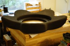
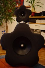
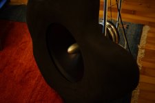
Please find a teaser again attached. I believe that the relative thick and non-resonant EVA-baffles contribute to the results primarly, and I have to thank Jeshi again for pointing me in this direction.
However, the building of the bass flowers was a lot of work, the final finish has yet to be done, but I´m realy glad all turned out this way for now, as I have invested considerable amounts of time, work (just calculated yesterday for fun: the routing alone was app. 800 metres...) and money.
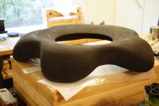
I think Perceval wanted to see my bass solution, so here it is: Acoustic Elegance Dipole 18, double 8-Ohm coil, in a flower baffle of max. 930 mm diametre, 160 mm depth, isolated from driver with sorbothane, free swinging, passive filter.
All the best
Mattes
thanks for posting your measurements, interesting work. Seems to be consistent with theory, and I find it interesting that your worst-case experiment (the circular baffle with sharp edges) doesn´t turn out THAT bad. This is consistent with my own experience; a circular baffle is, despite it´s very negative image, not that bad at all, given all edges are well rounded.
Sadly, all my old (less scientific approach, more to re-check what I was hearing) measurements are gone in a HD crash, and I have no new measurements yet.
So, when listening to music, I found (or maybe illusioned it only, who knows?) that the symmetrical behaviour (as in contrast to a rectangular baffle, which has different dispersion properties in the horizontal and in the vertical plane) has advantages in recreating the musical illusion, due to better imaging.
The flowers made it all a lot better again, in fact I was deeply surprised by the amount of improvements.
So, I worked really hard on the bass flowers (and therefore didn´t start any threads yet...) and mounted them yesterday... and then I couldn´t stop listening to music, as I was totally overwhelmed again by much unexpected improvements not only in the bass region, but in the whole bandwith, don´t know why (the DIPOLE 18 works up to 350 Hz and has a smooth B2 filter only). The finish is not perfect yet, but I had to listen to the flowers...
The initial inspiration came from the petal whizzer cone of my wideband units, all I do is copying/transferring the idea.
Jeshi, your stars will work fine for sure as well. As long as you have a decent amount of path variation and a decent roundover (some claim a minimum radius of 10% baffle width is needed), I do not think that you´ll need to hit a specific point. But, maybe I´ll get corrected by your experiments...
Please find a teaser again attached. I believe that the relative thick and non-resonant EVA-baffles contribute to the results primarly, and I have to thank Jeshi again for pointing me in this direction.
However, the building of the bass flowers was a lot of work, the final finish has yet to be done, but I´m realy glad all turned out this way for now, as I have invested considerable amounts of time, work (just calculated yesterday for fun: the routing alone was app. 800 metres...) and money.
I think Perceval wanted to see my bass solution, so here it is: Acoustic Elegance Dipole 18, double 8-Ohm coil, in a flower baffle of max. 930 mm diametre, 160 mm depth, isolated from driver with sorbothane, free swinging, passive filter.
All the best
Mattes
Attachments
- Status
- This old topic is closed. If you want to reopen this topic, contact a moderator using the "Report Post" button.
- Home
- Loudspeakers
- Full Range
- EVA foam for performance speaker enclosures