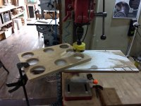
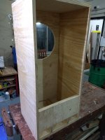
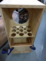
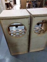
The best plywood I could get locally was marine grade pine, which requires some bracing in order to compensate for its softness.
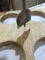
So, I decided to mix the types of wood used for bracing. The center piece seen on these pictures are the same ply, but all additional bracing is a local hard wood, called Angelim.
I guess it's likely to be a good approach, but difficult to maintain dimensional consistency.
Even though I'm happy with the results, I would design parts using a different strategy if I knew upfront how the various pieces would interact.
Attachments
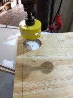
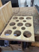
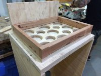
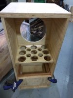
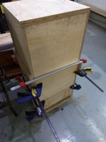
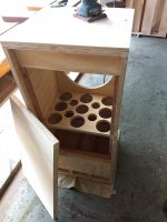
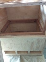
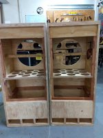
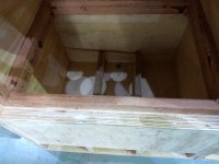
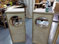
Here you can see how all pieces are assembled and glued to the main body.
Glue choice was not the best, given I used some expansive PUR in places that displaced parts a little bit in ways it required a lot of attention to get it right.
This is, of course, hand made work that is supposed to be imperfect, but I would strongly recommend to stay away from expansive types of glues, speacially on wall joints. PVA glue is king in that area, as it contracts and will give you a very tight bond.
Attachments
-
 IMG_20211201_205124069.jpg430.9 KB · Views: 69
 -
 IMG_20211201_205152768.jpg353.2 KB · Views: 75
 -
 IMG_20211203_182808611.jpg452.1 KB · Views: 69
 -
 IMG_20211203_212343980.jpg298.1 KB · Views: 72
 -
 IMG_20211203_212346260.jpg394.8 KB · Views: 77
 -
 IMG_20211203_213723133.jpg377.8 KB · Views: 65
 -
 IMG_20211204_141503320.jpg490.5 KB · Views: 63
 -
 IMG_20211204_143300875.jpg446.2 KB · Views: 82
 -
 IMG_20211210_160849408.jpg503.1 KB · Views: 89
 -
 IMG_20211210_160905233.jpg406.7 KB · Views: 76
 -
 IMG_20211210_160917677.jpg299.8 KB · Views: 76
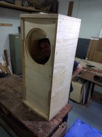
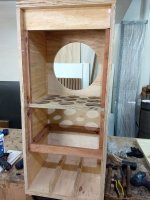
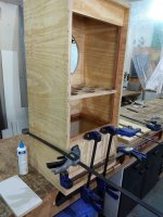
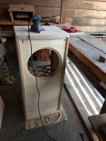
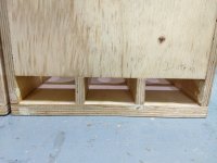
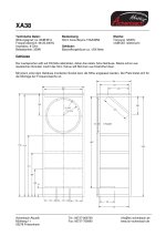
I also got in trouble with the vent, the way I designed it in the drawing you can see above.
I realized it would be difficult to place that kind of duct temporarily in a reliable way to test the enclousure, as the cut out was not very good and I didn't want to risk having a loose vent during tests.
The idea of having a removable back panel serves this purpose, of course, allowing for several adjustment cycles without the need to remove the loudspeaker.
So I decided to change the design to slotted vents, which makes it very easy to adjust with a single piece of ply just over the slots.
But the whole thing became a bit too complex, and it's probably a good idea to simplify the design by reducing the number of components, hence reducing errors and the need for adjustments.
Very nice experience so far.
I'll put some more pictures and info on speakers, once the installation starts.
Cheers!!
Attachments
NiToNi and crtex99,Looks great. Been running the Beymas for a while now - interested to hear about Xover optimisation as you go with this project.
Thanks for the comments.
crtex99,
I actually ordered a very simple 12dB/Oct crossover @ 1KHz, applying 6dB attenuation via LPAD for the tweeter.
It's coils have ferrite cores (I know....), which will limit power to about 160W RMS - not a problem to me, as my intention is to use low powered tube amps. Besides, coil size is reduced by using ferrite cores, and according to the builder it is easier to find the right capacitors for this configuration (I don't remember the specifics on this, but I had crossovers with ferrite cores in the past and I remember the results were good).
Very good construction anyway; the guy who built it is focused on automotive audio, but did a good job in my opinion, including measuring the frequency response of the final device.
This is the "fast and simple" solution, but I keep a separate 4 poles speakon connector in order to experiment with crossover points / slopes / etc further down the line. I'm going to install two high current DPST switches between the crossovers and the second 4 pole connector, which will allow me to completely disconnect the crossover from the speakers connectors and then have an external crossover connected, or going bi-amp.
I also bought a measurement microphone to run various tests using digital crossovers and try to find an optimised solution, before investing money in an electronic crossover + amps.
This is low in priority at the moment, as I'm putting all efforts into finishing the cabinets and installation of the drivers, cables and connectors.
Once I bring these monsters home, then I can start messing around with the electronic crossover. Final objective is biamping, once I figure out the best configuration.
All the best and happy holidays to you!
Hello All!
A lot happened since my last update, and I would like to announce the good news right away: the speakers are finished and playing for 11 weeks now.
For those willing to try these Beymas, be patient. These are rugged pro speakers, and they take a long time to break in, especially if you are using low power amps, which is my case. A pair of 15W RMS Quad II drives these speakers at party level volumes quite easily. Sound is very clear and defined when playing loud! I would describe it's character as concert-like, punchy and lively. Bass is dry and clear, and will reveal itself depending on the recorded material; if it's there, it's going to come out clean and strong.
Bass took a long time to open up (~9 weeks, which corresponds to some 200 hours for me). Speaker positioning makes a big difference, possibly as a consequence of the back firing port. Lots of direct radiation from the speaker cone gives well defined mid-bass.
The tweeter can be very sharp when new. Sound has improved significantly after ~100 hours.
As previously described, I'm using a very simple crossover, so there is room for improvement. Two aspects I would like to explore are Baffle Step Compensation, and the tweeter seems to have a peak in the mid-high range which possibly requires some attention.
I'll post pictures and describe the process as time allows.
It was an amazing journey and I am very happy with the results.
By far the best speakers I have designed and built so far.
Enjoy a few pictures below.
Embedded magnets for optional grille:


Here you can see the skirts plus wooden blocks to receive rubber feet underneath the speakers:


Just testing the size for one of the switches to disconnect the crossover from the speakers (more on that later):

DYI EVA gaskets:


A lot happened since my last update, and I would like to announce the good news right away: the speakers are finished and playing for 11 weeks now.
For those willing to try these Beymas, be patient. These are rugged pro speakers, and they take a long time to break in, especially if you are using low power amps, which is my case. A pair of 15W RMS Quad II drives these speakers at party level volumes quite easily. Sound is very clear and defined when playing loud! I would describe it's character as concert-like, punchy and lively. Bass is dry and clear, and will reveal itself depending on the recorded material; if it's there, it's going to come out clean and strong.
Bass took a long time to open up (~9 weeks, which corresponds to some 200 hours for me). Speaker positioning makes a big difference, possibly as a consequence of the back firing port. Lots of direct radiation from the speaker cone gives well defined mid-bass.
The tweeter can be very sharp when new. Sound has improved significantly after ~100 hours.
As previously described, I'm using a very simple crossover, so there is room for improvement. Two aspects I would like to explore are Baffle Step Compensation, and the tweeter seems to have a peak in the mid-high range which possibly requires some attention.
I'll post pictures and describe the process as time allows.
It was an amazing journey and I am very happy with the results.
By far the best speakers I have designed and built so far.
Enjoy a few pictures below.
Embedded magnets for optional grille:
Here you can see the skirts plus wooden blocks to receive rubber feet underneath the speakers:
Just testing the size for one of the switches to disconnect the crossover from the speakers (more on that later):
DYI EVA gaskets:
Here you can see the enclosures with applied veneer and finished with wood sealer + pigment.
A friend helped me with the veneering, as it requires more advanced skills to do it properly.
As my execution had several interruptions as a consequence of the need to travel, I decided to let him do this part before I finished the cabinet internally.
In the end, I probably saved a few days, but I don't recommend this approach.
It makes it to risky to move the cabinet around for other activities.


Installation of the skirt:


Speaker installation method
After a conversation with a friend who is in the pro audio market, I was convinced that the blind nut approach was the best, for two reasons:
1. It makes for a precise mechanical mount using machine screws (these look nice too, with the hexagonal heads matching the speaker visually);
2. In case I need to do any maintenance, the threads will be preserved when removing and mounting the speakers back to the cabinet.
It is important to install them by turning the screw from one side, and holding the nut in position at the other. That puts the nut in the correct position for a tight installation and angle to receive the screw (it probably works better than using the hammer to install the blind nuts). Drilling the holes with correct size is also important (I used a 7mm drill for 6mm M6 machine screws and it was just perfect: the nut goes in under pressure and I had no problems matching the speaker holes. I used the speaker itself as a template for drilling).


A friend helped me with the veneering, as it requires more advanced skills to do it properly.
As my execution had several interruptions as a consequence of the need to travel, I decided to let him do this part before I finished the cabinet internally.
In the end, I probably saved a few days, but I don't recommend this approach.
It makes it to risky to move the cabinet around for other activities.
Installation of the skirt:
Speaker installation method
After a conversation with a friend who is in the pro audio market, I was convinced that the blind nut approach was the best, for two reasons:
1. It makes for a precise mechanical mount using machine screws (these look nice too, with the hexagonal heads matching the speaker visually);
2. In case I need to do any maintenance, the threads will be preserved when removing and mounting the speakers back to the cabinet.
It is important to install them by turning the screw from one side, and holding the nut in position at the other. That puts the nut in the correct position for a tight installation and angle to receive the screw (it probably works better than using the hammer to install the blind nuts). Drilling the holes with correct size is also important (I used a 7mm drill for 6mm M6 machine screws and it was just perfect: the nut goes in under pressure and I had no problems matching the speaker holes. I used the speaker itself as a template for drilling).
Last edited:
Sealing and front baffle additional layer
I sealed the cabinet using a polyurethane based product. I used a leftover to damp two internal walls, but I was not able to confirm its effectiveness as a damper - no empirical evidence so to say, these walls sounded the same as others to me when knocking; no proper measurement instruments though...
I installed this piece of bracing exactly at the center of the speaker and added a hard polymer "foot" to lock the bracing against the woofer magnet. It seems to work very well. As you guys know, the idea is to break the size of the lateral wood panels to smaller "rectangles", hence raising the center frequency of resonances and making the panels less prone to excitation from the speaker back waves.
I can say very little vibration can be felt if you touch the walls during heavy bass passages. Another interesting aspect is that the 30mm thickness top and bottom seems to behave similarly to 20mm thick walls (maybe an effect of my bracing strategy?).

I also added neoprene tape as a sealer for the back panel:

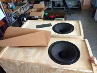
My approach to reduce front baffle reflection/diffraction (not sticking to any precise definition here) was to cover it with a 5mm thick cork layer and have the speaker flash mounted. The cork also gives the speakers a very nice look.


It was very easy to open the speaker hole with a router since it was just a matter of using the cutout as a reference, and remove the lateral excess with a knife.


When I routed the speaker outer diameter, I made a mistake and took out some 3mm in excess depth (see post #60). So I added one MDF ring to each baffle compensate that, as you can see above (black layer from laser cut CNC). In the end, that extra layer provided an almost perfectly flat surface to accommodate the speaker.
With all pieces properly glued together, I ended up with a very tight fit for the speaker after adding the gaskets.
I sealed the cabinet using a polyurethane based product. I used a leftover to damp two internal walls, but I was not able to confirm its effectiveness as a damper - no empirical evidence so to say, these walls sounded the same as others to me when knocking; no proper measurement instruments though...
I installed this piece of bracing exactly at the center of the speaker and added a hard polymer "foot" to lock the bracing against the woofer magnet. It seems to work very well. As you guys know, the idea is to break the size of the lateral wood panels to smaller "rectangles", hence raising the center frequency of resonances and making the panels less prone to excitation from the speaker back waves.
I can say very little vibration can be felt if you touch the walls during heavy bass passages. Another interesting aspect is that the 30mm thickness top and bottom seems to behave similarly to 20mm thick walls (maybe an effect of my bracing strategy?).
I also added neoprene tape as a sealer for the back panel:
My approach to reduce front baffle reflection/diffraction (not sticking to any precise definition here) was to cover it with a 5mm thick cork layer and have the speaker flash mounted. The cork also gives the speakers a very nice look.
It was very easy to open the speaker hole with a router since it was just a matter of using the cutout as a reference, and remove the lateral excess with a knife.
When I routed the speaker outer diameter, I made a mistake and took out some 3mm in excess depth (see post #60). So I added one MDF ring to each baffle compensate that, as you can see above (black layer from laser cut CNC). In the end, that extra layer provided an almost perfectly flat surface to accommodate the speaker.
With all pieces properly glued together, I ended up with a very tight fit for the speaker after adding the gaskets.
Last edited:
GM,Rigidity increases at the cube of thickness, so with only an added 10 mm, kind of surprised you can tell any real difference.
Thanks for the info!
Maybe I gave the wrong impression by the way I wrote my text.
I meant I cannot tell any difference (feels like more or less the same to me).
So that means, apart from having some extra material to flush mount the woofer on the front baffle, 30mm thickness makes no sense at all... a bit too late for me, but the final result looks good anyway.

By the way, I read many of your posts when doing my research. Thank you for sharing so much valuable knowledge. It really helped me a lot when developing this project.
Cheers!
Internal Stuffing
After installing the cork layer on the front, this is how they look:

Time to install internal stuffing. I chose 10mm automotive felt for the walls and 50mm thick PET wool for the top and back panels. PET wool is a recycled material designed especially for acoustic treatment. In my opinion, it is better to work with than glass or rock wool, because it doesn't irritate the skin, it is hypoallergenic and non-toxic. I left the last segment at the bottom without any stuffing at all. Contact adhesive was used to put the absorbing materials in place.


Speaker Installation


After installing the cork layer on the front, this is how they look:
Time to install internal stuffing. I chose 10mm automotive felt for the walls and 50mm thick PET wool for the top and back panels. PET wool is a recycled material designed especially for acoustic treatment. In my opinion, it is better to work with than glass or rock wool, because it doesn't irritate the skin, it is hypoallergenic and non-toxic. I left the last segment at the bottom without any stuffing at all. Contact adhesive was used to put the absorbing materials in place.
Speaker Installation
Testing and Tuning the Cabinets
Almost finished, this is how they looked:

Here we can see the hard polymer foot pressing against the speaker magnet:

The DATS was connected directly to the woofers and I clamped the back panel to tune the port to the correct length:

After a few rounds to make it shorter, I got it tuned quite close to the woofers' Fs. Simulations from Troels spreadsheet and other software were quite close, I must say.
Previously, I measured the woofers in free air conditions, in order to check their Fs. I guess my improvised test equipment is far from ideal, having this old laptop connected to the DATS and the whole thing behaving a bit unpredictable, starting with the calibration resistor, that seemed to give different results every time I tried to calibrate (maybe some connection is bad inside as a consequence of international shipping, I don't know...).
But I had to move on, so I ran the tests a few times to make sure I got the same results at least twice, and succeded to some extent. Maybe not as precise as it could be, but good enough for the purpose.
These are the free air impedance curves:
Speaker 1

Speaker 2

Fs is pretty close to factory spec, just a couple of Hertz off. And that's before breaking in.
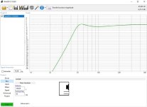
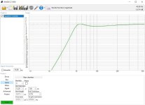
And these are the curves for the tuned cabs:

I tuned it spot on the speakers nominal Fs, in an attempt to achieve a classic Bass Reflex tuning. Later on, after woofers broke in, the tuning point changed a couple of Hertz lower, as you are going to see ahead.
Now, there's this peak @ about 160Hz I didn't pay too much attention to, considering the ugliness of the traces and a couple of ohms didn't seem to be too much of a big deal. By the way, there are some nasty peaks all over the place - including the free air measurements -, so I was thinking maybe this is a result of the poorly set up of the test equipment.
Reading about impedance curves later, I learned this can be caused by resonances resulting from wall dimensions in the cabinet, and the quarter wave length of that frequency could give some indication of the origin of the problem. If I'm correct, that would be close to 52cm, which corresponds to the distance between the front baffle and the back panel. So, perhaps that back panel requires some additional treatment.
I didn't treat this particular issue yet, as I have a few bigger ones to deal with, as we are going to see ahead (LOL).
Anyway, any help from you guys is appreciated. I'm, of course, feeling I should just relax and enjoy the results for a while, as I cannot tell there is a problem unless I look at the plot - maybe an improvement in that impedance curve would be relevant enough to make the effort and open the cabinets to further damp the internal walls. Please, share your thoughts. The peak amplitude is about 2-3 ohms, measuring from the lowest point before it.
Next post will be about cable testing, which in my opinion made a very noticeable difference from one to another, and I believe it's going to touch on a slightly controversial topic, given the strong opinions people hold on either speaker cables actually make a difference or not (here we go again).
Cheers!
Almost finished, this is how they looked:
Here we can see the hard polymer foot pressing against the speaker magnet:
The DATS was connected directly to the woofers and I clamped the back panel to tune the port to the correct length:
After a few rounds to make it shorter, I got it tuned quite close to the woofers' Fs. Simulations from Troels spreadsheet and other software were quite close, I must say.
Previously, I measured the woofers in free air conditions, in order to check their Fs. I guess my improvised test equipment is far from ideal, having this old laptop connected to the DATS and the whole thing behaving a bit unpredictable, starting with the calibration resistor, that seemed to give different results every time I tried to calibrate (maybe some connection is bad inside as a consequence of international shipping, I don't know...).
But I had to move on, so I ran the tests a few times to make sure I got the same results at least twice, and succeded to some extent. Maybe not as precise as it could be, but good enough for the purpose.
These are the free air impedance curves:
Speaker 1
Speaker 2
Fs is pretty close to factory spec, just a couple of Hertz off. And that's before breaking in.
And these are the curves for the tuned cabs:
I tuned it spot on the speakers nominal Fs, in an attempt to achieve a classic Bass Reflex tuning. Later on, after woofers broke in, the tuning point changed a couple of Hertz lower, as you are going to see ahead.
Now, there's this peak @ about 160Hz I didn't pay too much attention to, considering the ugliness of the traces and a couple of ohms didn't seem to be too much of a big deal. By the way, there are some nasty peaks all over the place - including the free air measurements -, so I was thinking maybe this is a result of the poorly set up of the test equipment.
Reading about impedance curves later, I learned this can be caused by resonances resulting from wall dimensions in the cabinet, and the quarter wave length of that frequency could give some indication of the origin of the problem. If I'm correct, that would be close to 52cm, which corresponds to the distance between the front baffle and the back panel. So, perhaps that back panel requires some additional treatment.
I didn't treat this particular issue yet, as I have a few bigger ones to deal with, as we are going to see ahead (LOL).
Anyway, any help from you guys is appreciated. I'm, of course, feeling I should just relax and enjoy the results for a while, as I cannot tell there is a problem unless I look at the plot - maybe an improvement in that impedance curve would be relevant enough to make the effort and open the cabinets to further damp the internal walls. Please, share your thoughts. The peak amplitude is about 2-3 ohms, measuring from the lowest point before it.
Next post will be about cable testing, which in my opinion made a very noticeable difference from one to another, and I believe it's going to touch on a slightly controversial topic, given the strong opinions people hold on either speaker cables actually make a difference or not (here we go again
).Cheers!
Last edited:
It seems my problem is somewhere else then...Sheesh! All that just to find Fs! All we ever did was do a slow frequency sweep in the general area and when the driver stopped moving we had Fs.
Eigenmodes/standing waves are 1/2 WL, so 34400/2/52 = ~331 Hz
Searching a little bit further, I found this article which describes three possible explanations for this type of glitch in a bass reflex enclosure (figure 26): port tube resonance, cabinet vibration, or a standing wave.
https://audioxpress.com/article/testing-loudspeakers-which-measurements-matter-part-2
Coincidently, the anomaly seems to be close the the one observed in my plot, centered between 160Hz and 170Hz.
The internal height for my enclosure is 105cm, which would correspond to 163.8Hz.
So, it seems to explain the problem.
Now, this article explains how to treat it:
https://audiojudgement.com/internal-standing-waves/
Not sure if there's something I can do about it, because I had to change my design to slot vents during execution, meaning I cannot add any materials to the bottom of the enclosure.
Last edited:
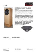
Nice driver I think.
I simulated an existing design.
They say ~120 liter.
BR tuning 50 Hz.
3x BR ports each 13,2 x 7 cm, length ~20cm.
~46 Hz @ -3dB..
I simulated an existing design.
They say ~120 liter.
BR tuning 50 Hz.
3x BR ports each 13,2 x 7 cm, length ~20cm.
~46 Hz @ -3dB..
Attachments
Awesome & beautiful speaker project!
Re. speaker cable,
as you probably know the lower your impedance 'dips' are, the more speaker cable can be heard.
The 'basic golden rule' is you just buy the heaviest gauge OFC copper you can afford.
If you find light gauge sounds better, then you are compensating for something 'not quite right'
with the speaker, amp. or both. (even the room)
CHEERS
- Home
- Loudspeakers
- Full Range
- Speakers based on Beyma 15XA38ND