X,
The 3 pics in portrait mode look fat and squished vertically in the post, but the height and width becomes ok when you click on them. These are: Speaker front, speaker baffle with close up of drivers, speaker back.
The other three of the pics are in landscape orientation, but not necessarily wrong. Those are: pic of the empty box with dampening sheets, pic of the plywood dagger cab, and pic of box with egg-crate foam lining and XO installed in cab.
X,
The 10F/8424 appears to be centered in the baffle in your new photos, but if I remember correctly in the original version of this speaker it was offset from center, presumably to minimize baffle edge diffraction. Is there a specific reason it is now positioned in the center of the baffle? Did the offset position seem to work differently, or do you notice no difference with the driver now centered?
The 10F/8424 appears to be centered in the baffle in your new photos, but if I remember correctly in the original version of this speaker it was offset from center, presumably to minimize baffle edge diffraction. Is there a specific reason it is now positioned in the center of the baffle? Did the offset position seem to work differently, or do you notice no difference with the driver now centered?
This is a dirty quick simulation using the edge to show difference when 10F is positioned offset or into center of baffle, grey trace at 60dB number on Y axis show the difference response between the two positioning and above that is green trace measured response from post 1 where 10F was offset positioned and another grey trace overlaid that show difference curve added to green trace.
Think positioning in center of baffle often is relative worse than off-center trick, but for center position it seems errors become symmetric same relative to left or right side of speaker so EQ correction will work, where off-center position seems will need different EQ correction scheme relative to left or right side of speaker.
Think positioning in center of baffle often is relative worse than off-center trick, but for center position it seems errors become symmetric same relative to left or right side of speaker so EQ correction will work, where off-center position seems will need different EQ correction scheme relative to left or right side of speaker.
Attachments

Last edited:
Is the dagger 4 sided? Curious about the internal dimensions as well. I'm planning on making some for mine when I order the 10f's
I wanted 3-sided (6in x 12in triangles) originally but with the 0.5in radius round-over on the back of the baffle for good air flow, the Dagger mouth could not accommodate the enlarged diameter. It would have to be made very large. So I compromised with a 4-sided dagger still 6in base x 12in tall. Once built, the vertex clears the back of the cabinet by about 3/8in - a perfect fit. There is still enough room for my fairly bulky XO in the space next to the Dagger on the floor of the cabinet.
X,
The 10F/8424 appears to be centered in the baffle in your new photos, but if I remember correctly in the original version of this speaker it was offset from center, presumably to minimize baffle edge diffraction. Is there a specific reason it is now positioned in the center of the baffle? Did the offset position seem to work differently, or do you notice no difference with the driver now centered?
The reduced baffle diffraction is minor (thanks to Byrtt for simulating that) compared to how many people visually like a symmetric looking speaker. If you look at most commercial speakers nowadays, they have pretty much gone away from offset tweeters. It makes production easier too as there is only one design. The visual aesthetic is an important overall requirement. But in terms of sheer performance, offset is better and even better is a trapezoid.
I wanted 3-sided (6in x 12in triangles) originally but with the 0.5in radius round-over on the back of the baffle for good air flow, the Dagger mouth could not accommodate the enlarged diameter. It would have to be made very large. So I compromised with a 4-sided dagger still 6in base x 12in tall. Once built, the vertex clears the back of the cabinet by about 3/8in - a perfect fit. There is still enough room for my fairly bulky XO in the space next to the Dagger on the floor of the cabinet.
Awesome, as mine is going to be exposed, I'm making it 3 sided, using 25mm baltic birch. I'll keep the interior dimensions 6" x 12" (~150mm x ~300mm).
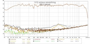
Some preliminary measurements of the new BB cabinet (left) vs the XPS cabinet (right), so not exact same drivers but the XPS boxes measured pretty close before.
Using a VHEX+ amp, Focusrite 2i4 DAC for source, and UMIK-1 microphone with Cross Spectrum Labs calibration, Dr Meter absolute SPL meter. Taken at woofer axis 0.5m awat and 2.83vrms as measured with Fluke DVM with 1kHz sine wave.
Here is the XPS speaker distortion as a function of frequency:

The bump in H3 distortion at 3kHz is from the woofer - I know this because when the XO was outside (with the XPS cab), I was able to measure just the woofer only.
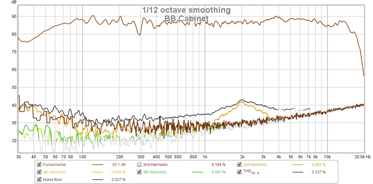
Here is the new BB speaker distortion as a function of frequency:
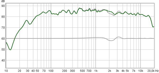
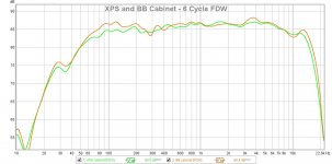
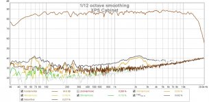
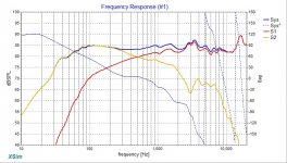
Here is overalay of the frequency response between the two:
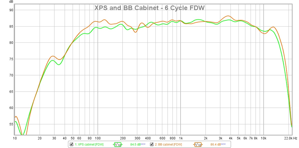
It looks like the stiffer box gained about 2dB of bass output at 100Hz, and the bass distortion went down. The XPS box appears to have a smoother response in general. Not bad for a lightweight foam box. The BB cabinet has a sharp notch appearing at about 280Hz, and a notch at 10kHz. I am not sure what is causing the 280Hz notch other than floor bounce - but then why is nit not on the XPS? The 10kHz dip might be a reflection from the cone to the thick edge of the baffle. I did put a 0.5in radius round-over internally. But overall bass presentation is probably more accurate and less noise with the new cabinet.
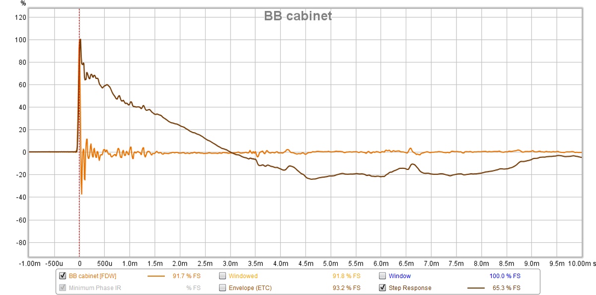
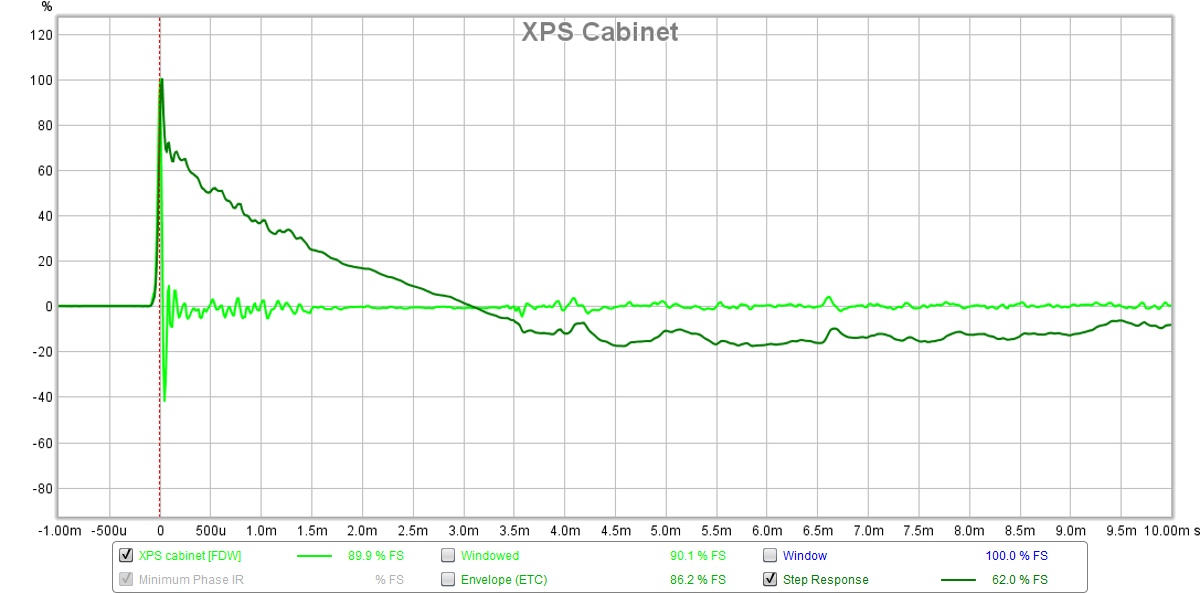
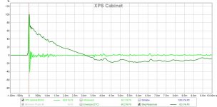
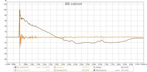
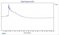
The step response of the BB cabinet seems to have a more right-angle looking triangle vs the XPS foam which had a slight sag. I suppose this can be interpreted as a more direct percussive quality.
SR for BB:
SR for XPS:
Using a VHEX+ amp, Focusrite 2i4 DAC for source, and UMIK-1 microphone with Cross Spectrum Labs calibration, Dr Meter absolute SPL meter. Taken at woofer axis 0.5m awat and 2.83vrms as measured with Fluke DVM with 1kHz sine wave.
Here is the XPS speaker distortion as a function of frequency:
The bump in H3 distortion at 3kHz is from the woofer - I know this because when the XO was outside (with the XPS cab), I was able to measure just the woofer only.
Here is the new BB speaker distortion as a function of frequency:
Here is overalay of the frequency response between the two:
It looks like the stiffer box gained about 2dB of bass output at 100Hz, and the bass distortion went down. The XPS box appears to have a smoother response in general. Not bad for a lightweight foam box. The BB cabinet has a sharp notch appearing at about 280Hz, and a notch at 10kHz. I am not sure what is causing the 280Hz notch other than floor bounce - but then why is nit not on the XPS? The 10kHz dip might be a reflection from the cone to the thick edge of the baffle. I did put a 0.5in radius round-over internally. But overall bass presentation is probably more accurate and less noise with the new cabinet.
The step response of the BB cabinet seems to have a more right-angle looking triangle vs the XPS foam which had a slight sag. I suppose this can be interpreted as a more direct percussive quality.
SR for BB:
SR for XPS:
Attachments
Last edited:
") .
.X,
I congratulate you on this project. It appears to be a well-thought-out design. Indeed, your contributions to this forum are a large part of what makes it interesting to me.
I took particular interest in this thread because I recently had an idea for a speaker that is somewhat similar to what you have presented here. I would appreciate any comments or suggestions you might have in regard to my proposed design.
I have a pair of Dayton Audio 22 liter MDF cabinets (17"H X 10"W X 12"D exterior dimensions) that I bought years ago for a project that did not succeed. I had purchased spare baffles for it (they are removable), so I now have two complete cabinets that I wish to use to build an inexpensive sealed-cabinet stand-mounted close field monitor. My preference is to listen on axis and very close (one meter or less), so I need to insure that any drivers I use have a smooth response and can be mounted close enough to each other to conform to the quarter-wave crossover guideline. My intention is to use a simple first-order crossover with inexpensive inductors and capacitors in addition to drivers that give much value for the price. The drivers will have a two-octave flat FR extension beyond crossover and will be compensated for flat impedance. No components have yet been purchased.
My choice is to build a full range/woofer combination with the Peerless TC9FD18-08 and the Dayton Audio RS225-4. The 8-ohm TC9 is rated at 84dB/2.83V while the 4-ohm RS225 is rated at 91dB/2.83V. This combination should give me built-in baffle step compensation. I would cross the TC9 at 500Hz and the RS225-4 at 350Hz. With the available inductors from which I will choose for the crossover I should get about 2dB attenuation on the woofer, which I think will be about right for the baffle step with this cabinet and give me a summation with the TC9 close to 500Hz. Crossing the RS225-4 at 350 Hz should also reduce the upper-midrange/treble cone breakup to a level well below the summed output of the two drivers, and the added resistance of the inductor coil should give a Qts. value that would extend the low-frequency response. Again, the cabinet will be sealed, and I will use interior paint-on coating and stuffing in both the woofer compartment and the mid-tweet chamber (which, with the TC9, appears that it can be very small in volume). I would mount the TC9 above the RS225 to use with the speaker stands that I now own.
I don't expect transient-perfect behavior with this speaker, but I do intend to experiment with tipping the cabinet back in an attempt at time alignment of the two drivers. I simply want a smooth-sounding speaker that I can use in the very close field so that I can minimize the effects of the room upon the sound. I estimate the total cost of drivers and crossovers to be about $200.00 USD, and I don't want to spend much more than that.
Thoughts? Comments? Suggestions?
Last edited:
Majerjack,
Thanks for the interest in this thread and my other projects. This speaker is particularly smooth and that’s a great idea to go with a 4ohm for 91dB at 2.83v. Indeed, you may not need to pad the TC9FD and end up with an 86dB at 2.83v sensitive speaker. To cross at 500Hz probably requires a bigger than 4mH coil. Maybe look into an iron core one to keep price and size reasonable. Try 8mH to 10mH coil for RS225 and 100uF on the TC9 no padding resistors. Still use the Zobel though on TC9. So try my XO but boost the 50uF cap to 100uF. Use an electrolytic to test if it works before spending $ on film caps. Increase the coil to 8mH to 10mH. Looks like a nice project.
Thanks for the interest in this thread and my other projects. This speaker is particularly smooth and that’s a great idea to go with a 4ohm for 91dB at 2.83v. Indeed, you may not need to pad the TC9FD and end up with an 86dB at 2.83v sensitive speaker. To cross at 500Hz probably requires a bigger than 4mH coil. Maybe look into an iron core one to keep price and size reasonable. Try 8mH to 10mH coil for RS225 and 100uF on the TC9 no padding resistors. Still use the Zobel though on TC9. So try my XO but boost the 50uF cap to 100uF. Use an electrolytic to test if it works before spending $ on film caps. Increase the coil to 8mH to 10mH. Looks like a nice project.
Cool speaker and measurements!
I don't feel like wadding through this large thread to find it, but do you have an impedance measurement for the 10F (or TC9) in the short tappered TL?
Have a look at an old thread of mine, where I put an FF85WK in a 12" tube and stuffed it to kill the impedance peak.
Stuffed midrange TL for high-passed FR drivers
I never did anything more the the initial exercise, but this would facilitate a passive Xo at low frequencies. I know TC9 already has a mild impedance peak due to its low Qm, so I guess it'd be easy to get it really flat, almost purely resistive.
Cool speaker and measurements!
I don't feel like wadding through this large thread to find it, but do you have an impedance measurement for the 10F (or TC9) in the short tappered TL?
Have a look at an old thread of mine, where I put an FF85WK in a 12" tube and stuffed it to kill the impedance peak.
Stuffed midrange TL for high-passed FR drivers
I never did anything more the the initial exercise, but this would facilitate a passive Xo at low frequencies. I know TC9 already has a mild impedance peak due to its low Qm, so I guess it'd be easy to get it really flat, almost purely resistive.
Back in Post 115, this is 10F in Dagger:
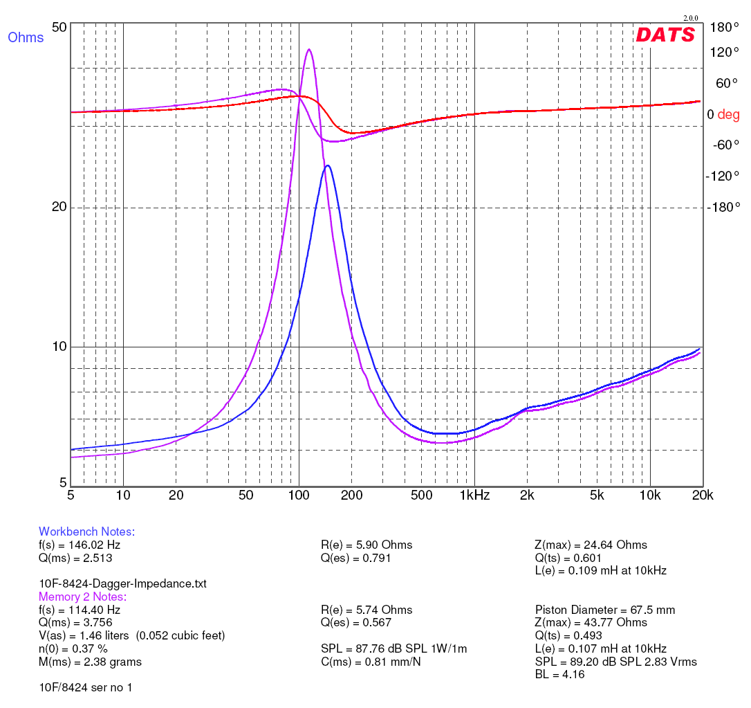
Looking back, it could probably use more fiberglass to flatten that peak even more. But I am highpassing way above 110Hz so that region is not that audible anyway.
Last edited:
I'm interesting in giving this design a try. I have a few things I'd like to do a little differently with the enclosure and I'm curious about everyone's input.
For drivers I'll be using a RS225 and TC9FD.
For the enclosure instead of a sealed box I'm going to use a ported one for more bass extension. The net volume will be 1.5 cu ft (42.5 liters) tuned to 30 Hz. Here is my tentative layout and dimensions.


I put in a stepped baffle to help get the RS225 a little bit ahead of the TC9FD.
The TC9FD will be in four-sided dagger stuffed with polyfil.
I've been wanting to try come CLD techniques, so I'm going to attach hardiboard to the interior of the enclosure. It will then get a layer of felt over the top of the hardiboard.
Anyway, I'd love to hear everyone's input!
For drivers I'll be using a RS225 and TC9FD.
For the enclosure instead of a sealed box I'm going to use a ported one for more bass extension. The net volume will be 1.5 cu ft (42.5 liters) tuned to 30 Hz. Here is my tentative layout and dimensions.
I put in a stepped baffle to help get the RS225 a little bit ahead of the TC9FD.
The TC9FD will be in four-sided dagger stuffed with polyfil.
I've been wanting to try come CLD techniques, so I'm going to attach hardiboard to the interior of the enclosure. It will then get a layer of felt over the top of the hardiboard.
Anyway, I'd love to hear everyone's input!
Hi Jessman,
That looks really nice and a good way to get deeper bass. My only concern is that the bass from a BR is not going to be tight from a time alignment standpoint. You get a lot of group delay (GD) at the lower frequencies and the sound of drum may not be as coherent.
If you want to do a stepped baffle with the tweeter on top, put the Dagger externally on its own trapezoidal baffle and move it back 3in.
Another option is to use dual RS225-8 in parallel (in 50L box) and then decrease padding on tweeter.
And yet another option is a tapered and stuffed PMC style labyrinth TL. Deep and tight low GD bass.
But, from simplicity standpoint - your tower BR is pretty good. It is tall enough to be ML-TL and that will sound better than a BR of same size.
Hi Jessman,
That looks really nice and a good way to get deeper bass. My only concern is that the bass from a BR is not going to be tight from a time alignment standpoint. You get a lot of group delay (GD) at the lower frequencies and the sound of drum may not be as coherent.
If you want to do a stepped baffle with the tweeter on top, put the Dagger externally on its own trapezoidal baffle and move it back 3in.
Another option is to use dual RS225-8 in parallel (in 50L box) and then decrease padding on tweeter.
And yet another option is a tapered and stuffed PMC style labyrinth TL. Deep and tight low GD bass.
But, from simplicity standpoint - your tower BR is pretty good. It is tall enough to be ML-TL and that will sound better than a BR of same size.
Thanks for the reply X!
I'll probably give it a try as shown, I know I'm going to get higher group delay, but it shouldn't rise above 10 ms until below about 40 Hz, I think I can live with that.
If nothing else I can measure it and see how it performs, if I don't like it I'll just build a different cabinet.
X,
Thank you for your reply. I will order the drivers, do some testing on them, and see what I can do. I appreciate your suggestions, and again, I commend you for your efforts on this forum.
Sorry, I may have given you some wrong figures here off the top of my head. The RS225-4 is 4ohms so the coil value actually worked out well to go to 2mH (cheaper and lighter). I did not have the FRD/ZMA files for the TC9 on hand so used the RS100-8 as a surrogate. You, could of course build one with the RS100-8 and it would sound quite nice.
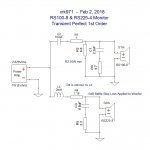
Here is the revised schematic for an RS225-4 and a RS100-8 midtweeter, I have already subtracted -5dB from the factory FRD file (which assumes a very large baffle). So look like overall efficiency is a true 84.5dB or thereabouts. Not bad.
Here is XO schematic:
Here is predicted FR:
Here is predicted electrical impedance and phase as seen by amp:
Here is predicted Step Response with tweeter having a 0.75in setback:
Byrtt will probably be able to do a better job at helping us to get the acoustic phase flatter. But the main thing is that you need a 2mH coil not 8mH!
Here is the coil I used for the sim:
Jantzen Audio 2.0mH 20 AWG Air Core Inductor Crossover Coil
For the 100uF cap, use two 50uF film in oil motor run caps in parallel, or two 220uF 100V electrolytics connected -+/+- or +-/-+ to act as non-polar.
Cheers,
X
Attachments
-
 RS100-8-RS22-4-FAST-500Hz-Transient-Perfect-XO.jpg88.9 KB · Views: 25,753
 -
 RS100-8-RS22-4-FAST-500Hz-Transient-Perfect-XO-FR.jpg148.4 KB · Views: 2,233
 -
 RS100-8-RS22-4-FAST-500Hz-Transient-Perfect-XO-Phase.jpg126.6 KB · Views: 2,202
 -
 RS100-8-RS22-4-FAST-500Hz-Transient-Perfect-XO-Step.jpg34.7 KB · Views: 2,560
Last edited:
I'm betting high on a reflection from the box's back wall.The BB cabinet has a sharp notch appearing at about 280Hz, and a notch at 10kHz. I am not sure what is causing the 280Hz notch other than floor bounce - but then why is nit not on the XPS?
- Home
- Loudspeakers
- Full Range
- 10F/8424 & RS225-8 FAST / WAW Ref Monitor