I'm onto this already. I am printing a test waveguide for 1in CD (90x40 deg SEOS) just to practice using the 3d print technology and will gin up a shallow waveguide for the 10F next. Possibly with 3d printed reticulated foam.
The passive version is just my curiousity with trying a passive design. I agree the port will make it worse but my models show only a minimal impact to the GD (circa 10ms) since I won't use a HPF or LT.
The passive version is just my curiousity with trying a passive design. I agree the port will make it worse but my models show only a minimal impact to the GD (circa 10ms) since I won't use a HPF or LT.
I've been eyeing that thread ") . I love 3D printing ever since I held my first printed model in hand back in 2005. From what I've seen the expensive commercial 3D printers win in texture and fine details but things are improving in the 3D affordable printers.
. I love 3D printing ever since I held my first printed model in hand back in 2005. From what I've seen the expensive commercial 3D printers win in texture and fine details but things are improving in the 3D affordable printers.
I've only used it for a waveguide for a Vifa XT tweeter for my car, printed trough Shapeways. I'd love to have access to one myself but rely on the expensive online services for now.
. I love 3D printing ever since I held my first printed model in hand back in 2005. From what I've seen the expensive commercial 3D printers win in texture and fine details but things are improving in the 3D affordable printers.I've only used it for a waveguide for a Vifa XT tweeter for my car, printed trough Shapeways. I'd love to have access to one myself but rely on the expensive online services for now.
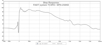
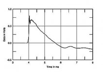
Sealed+1.order gives good SR
Talking waveguide have a when one have no 3D printer.
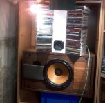
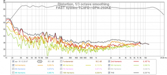
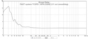
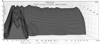
TC9FD combined SPH-250KE in a old CW box a project just for exercise.
XO 400Hz 1.order and EQ are handled inside JRiver but because present soundcard have only 2 channel ouput i'm in same boat as xrk971 having only one speaker but lucky enough JRiver can route/mix L&R to mono speaker.
Experience is same as X if not delay for tweeter was set precise SR is ruined and this one like exact 0,48mS.
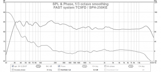
In region 80-200Hz have some room mode such outs and in i repair that with EQ at HD plot you see a bump up there, speaker is placed in a corner and measurement taken there, so guess it could be much better with some strategic placement.
Talking waveguide have a
when one have no 3D printer.TC9FD combined SPH-250KE in a old CW box a project just for exercise.
XO 400Hz 1.order and EQ are handled inside JRiver but because present soundcard have only 2 channel ouput i'm in same boat as xrk971 having only one speaker
but lucky enough JRiver can route/mix L&R to mono speaker.Experience is same as X if not delay for tweeter was set precise SR is ruined and this one like exact 0,48mS.
In region 80-200Hz have some room mode such outs and in i repair that with EQ at HD plot you see a bump up there, speaker is placed in a corner and measurement taken there, so guess it could be much better with some strategic placement.
Attachments
Byrtt,
Thanks for sharing. Those measurments look very nice. Speaking of waveguides, your two stacks of CD's placed around the speaker in a V shape may be acting as a waveguide for the TC9FD ? Yes, I was quite surprised how exacting the time alignment had to be to get a good SR. I know this may be very difficult to achieve with a passive system unless a semi variable all pass delay is used in addition to a 3in shift of the location of the tweeter behind the woofer. I see why cabinets sometimes have a back tilt. When the SR is set up just right - listening to percussion instruments sounds really realistic and "right". A fine nuance often not properly implemented on many speakers.
Thanks for sharing. Those measurments look very nice. Speaking of waveguides, your two stacks of CD's placed around the speaker in a V shape may be acting as a waveguide for the TC9FD
? Yes, I was quite surprised how exacting the time alignment had to be to get a good SR. I know this may be very difficult to achieve with a passive system unless a semi variable all pass delay is used in addition to a 3in shift of the location of the tweeter behind the woofer. I see why cabinets sometimes have a back tilt. When the SR is set up just right - listening to percussion instruments sounds really realistic and "right". A fine nuance often not properly implemented on many speakers.Wesayso,
Thanks for the background on what a good step response is supposed to look like. I guess I do have a winner! The time alignment was critical to get it clean just 0.26 ms to 0.22ms or 40 microseconds went from good to great. For a passive this probably means having a stepped baffle to get 10F behind the RS225 - kind of like T Graveson's Discovery 3-way monitor. That would avoid a complicated all pass delay. With passive there is really no choice but to put in a port to get some reflex bass action. I'm happy that a first order phase linear XO works. Much in part due to how flat the response of both drivers are through the XO region.
No, there is no EQ apart from the Linkwitz transform and level matching requiring a 6dB amplitude cut on the 10F. It saddens me to throw that kind of sensitivity away but also makes me wonder how run of mill passive speakers with drivers that are not as nice seem to get 88dB sensitivity ratings for the whole speaker?
So I have some help from Byrtt who has designed a passive XO for me that seems to match the measurement above. One thing he suggested trying was to take the predicted filter curve from the passive XO simulator (Xsim) and put it into miniDSP's filter dialog and see if it works before buying the parts. Is this something people do to check out XO's first?
That Stereophile link on Step Response says that the author has only measured a few speakers capable of a time coherent step response like this right triangle.
Fig.11 shows a good step response produced by a time-coherent, three-way loudspeaker, with the outputs of the three drive-units adding in-phase at the microphone position. There are not that many speakers that produce this good a step response. Of the speakers I have measured for Stereophile, only about 10—models from Quad, Thiel, Dunlavy, Spica, and Vandersteen—have step responses this go
Wow, that is pretty cool to be able to get SR this good.
Attachments
Last edited:
IIRC, a lot of times the sensitivity rating is for a fixed sine at 1khz. Years ago Danley made a very informative post about manufacturer specifications and how many different ways measurements are taken in order to paint the highest numbers regardless of real world accuracy.
For NF monitoring this speaker is looking *really good*. How does the 1st order cross sound?
/a
For NF monitoring this speaker is looking *really good*. How does the 1st order cross sound?
/a
IIRC, a lot of times the sensitivity rating is for a fixed sine at 1khz. Years ago Danley made a very informative post about manufacturer specifications and how many different ways measurements are taken in order to paint the highest numbers regardless of real world accuracy.
For NF monitoring this speaker is looking *really good*. How does the 1st order cross sound?
/a
Here are some sound clips with 1st order Butterworth at 350Hz electrical XO. No EQ except for Linkwitz transform on bass.
Stereo recording of right channel mono speaker. Change .asc to .mp3 to listen.
Attachments
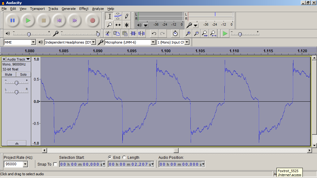
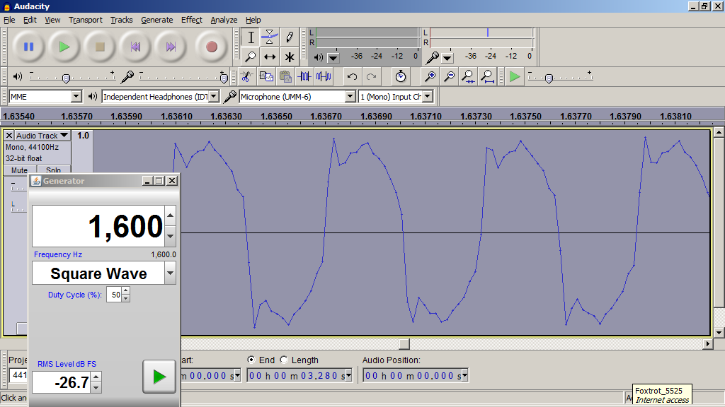
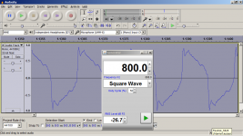
Got Square Waves?
I used Audacity to record the tone generator from REW set to square wave mode.
Screenshots of the .wav file at high resolution. It is not a perfect square wave but sort of looks like the step function sometimes. This is from 100Hz to 3200Hz (5 octaves).
100Hz:
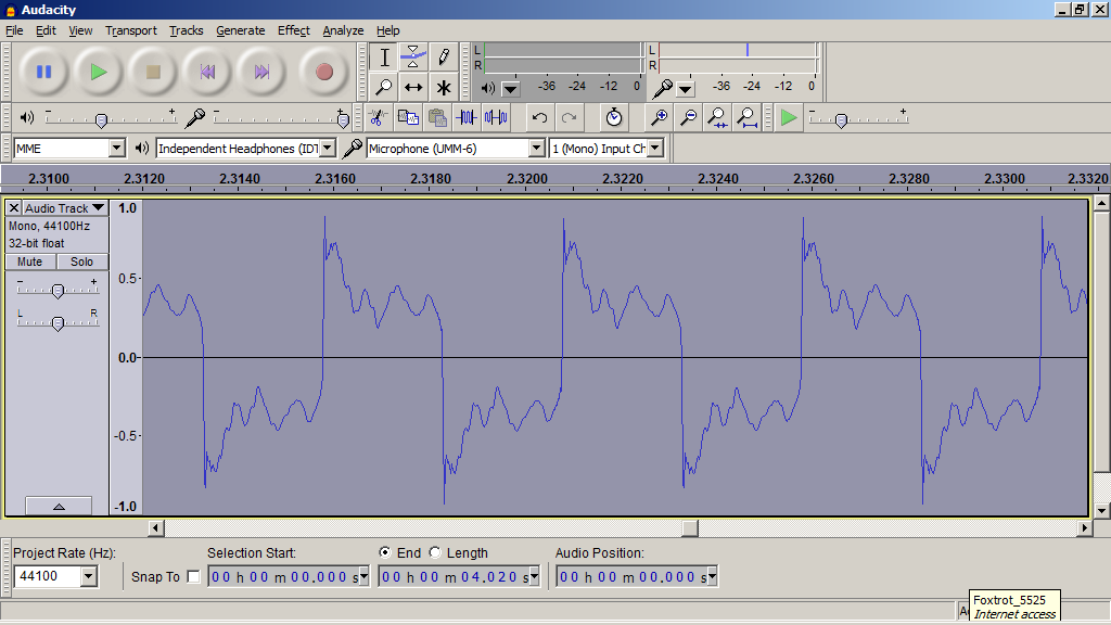
200Hz:
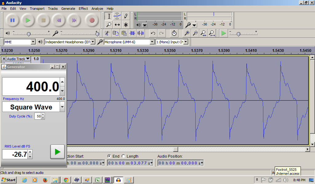
400Hz (near XO has a harder time):
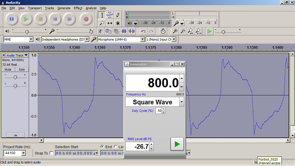
800Hz:
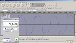
1600Hz:
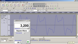
3200Hz:
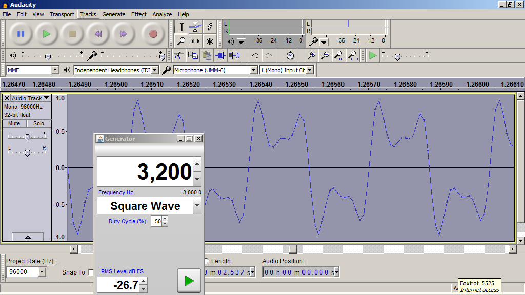
I think this actually looks pretty good as I have tried to do this before and not succeeded this well over a wide range. Only a linear phase variation speaker can do this.
I used Audacity to record the tone generator from REW set to square wave mode.
Screenshots of the .wav file at high resolution. It is not a perfect square wave but sort of looks like the step function sometimes. This is from 100Hz to 3200Hz (5 octaves).
100Hz:
200Hz:
400Hz (near XO has a harder time):
800Hz:
1600Hz:
3200Hz:
I think this actually looks pretty good as I have tried to do this before and not succeeded this well over a wide range. Only a linear phase variation speaker can do this.
Attachments

Last edited:
Here are some sound clips with 1st order Butterworth at 350Hz electrical XO. No EQ except for Linkwitz transform on bass.
Stereo recording of right channel mono speaker. Change .asc to .mp3 to listen.
Thanks sharing sound clips those some of your best
and impressed its without EQ. Makes one think could they be even better EQed a little and with another approach when setting up miniDSP and the slopes, then getting the squarer waves better at XO point.
Thanks sharing sound clips those some of your best
Makes one think could they be even better EQed a little and with another approach when setting up miniDSP and the slopes, then getting the squarer waves better at XO point.
Byrtt,
Thanks for the kind words about the SQ.
They do indeed sound very good and probably what they are supposed to sound like as envisioned by the recording engineer. What is interesting is when I play a recording of the speakers back through the speakers, it still sounds about like the first generation. The flat response and linear phase seems to allow more of this multi generational sound quality being preserved.
You have a good suggestion there: now that I have achieved what is a very good level of performance with minimal DSP other than XO and level balance, what else can I use in DSP to make this sound even better? Probably small PEQ's applied to smooth response and shape of slope at XO will make the XO region even more seamless and transparent? Would any hardware filters like a Zobel or impedance peak flattener be helpful in letting the active XO do its jobs even better?
I know DRC would help . Its generally good at solving problems, but even better at cleaning up an already good signal. Ideally you'd have a convolution on each separate driver creating the crossover with FIR filters. You'd need a multi channel sound card though and use that instead of the MiniDSP. Or one of the MiniDSP solutions with the convolution engine.
But is wouldn't harm to try and convolve a song to see what it can do with your current 2-way.
Why does there have to be some... isn't all recorded music going trough electronic devises before we can play it back? Why would the miniDSP be worse than running all of the signal trough passive components like resistors and capacitors? Which brand would you have to choose for components like that to please everyone?
I find it very strange that you'd suggest there has got to be some electronic haze in the miniDSP. But then again, you also claim that one bit perfect type of software isn't the same as another that's also bit perfect. A strange world we live in...
. Its generally good at solving problems, but even better at cleaning up an already good signal. Ideally you'd have a convolution on each separate driver creating the crossover with FIR filters. You'd need a multi channel sound card though and use that instead of the MiniDSP. Or one of the MiniDSP solutions with the convolution engine.But is wouldn't harm to try and convolve a song to see what it can do with your current 2-way.
Getting there. Except for the linkwitx transform, one could do this with a PLLXO and eliminate any electronic haze (there has to be some) from the miniDSP.
dave
Why does there have to be some... isn't all recorded music going trough electronic devises before we can play it back? Why would the miniDSP be worse than running all of the signal trough passive components like resistors and capacitors? Which brand would you have to choose for components like that to please everyone?
I find it very strange that you'd suggest there has got to be some electronic haze in the miniDSP. But then again, you also claim that one bit perfect type of software isn't the same as another that's also bit perfect. A strange world we live in...
Last edited:
I could not hear the difference with a signal going through a flat-lined miniDSP vs no miniDSP. I tried measuring if there was any difference in the audio signal and could not see a difference other than a slight improvement in the impulse response with the miniDSP in place. If there is "haze", my ears don't hear it. This study was posted a while back on one of my other "FAST" threads.
I am taking measurements at 0.5m and -6dB down from 2.83v or 0.71v. The HD will be lower overall but I don't expect a peak that you say would be there to not show up at all.
Maybe not but you need to measure at a level high enough and in a way that allows you to keep the signal to noise ratio high. You should see a clear difference between the 2nd, 3rd, 4th and 5th harmonics.
In most of your graphs the harmonics all blend together which shows a clear limitation with the way you're doing your measurements.
Attached are distortion measurements for the RS225 at 2.83vRMS. Here you can see the clear separation between the individual harmonics. If this isn't clear then you've got SnR issues.
Also doing distortion testing at such low drive levels (0.7v) isn't going to be capable of showing you limitations of whether or not your low order crossover (1st order) is actually performing adequately. Anyone could whack a 1st order, single cap, crossover on any tweeter and test it at a low drive level and the distortion would be low. To show whether or not it's enough you need to crank things up to represent what happens at high listening levels and/or during peaks/crescendos. Something like 90dB testing should be used as a minimum. For the RS225 this means a little higher than 2.83v nominal, with additional tests being performed at 100dB, 105dB and 110dB if the amplifier is capable of providing clean power that loud.
Attachments
The separation of the various harmonics in the distortion data has more to do with how I am presenting it on such a small compressed chart, not SNR of the signal. I take a lot of data at 0.5m to reduce effects of floor bounce but still keep an absolute SPL level comparable to manufacturers rating for comparison. I can take some at 1m and 2.83v if you are really interested in HD values there. I will also plot on another computer with larger screen to expand vertical scale. Let's see if the 1.2khz peak shows up.
Even with higher drive levels you need the mic close enough to the loudspeaker. 2.83v is great but the mic needs to be kept close for the SnR to increase.
You say your SnR is high enough but if that were the case then you'd have harmonics at -80dB or better. Yours flatline at around -60 showing that noise is limiting the resolution of your measurements.
You say your SnR is high enough but if that were the case then you'd have harmonics at -80dB or better. Yours flatline at around -60 showing that noise is limiting the resolution of your measurements.
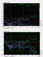
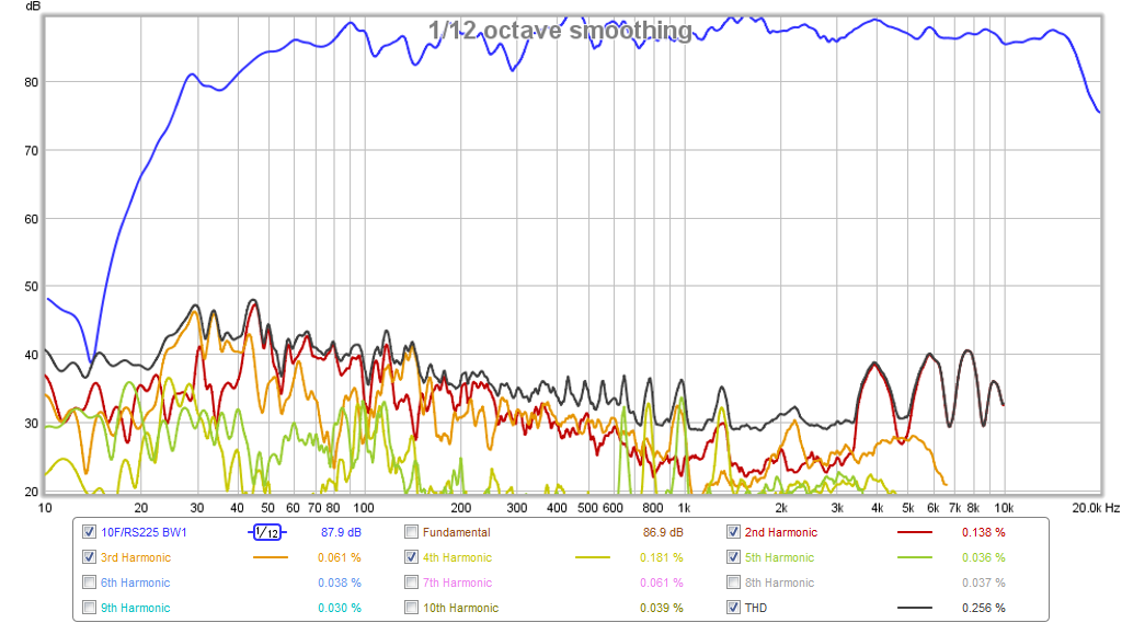
HD measurement at 2.83v and 0.5m
I took some new data here at 0.5m away (mic on axis of 10F) and 2.83v drive. Note that there is -6dB cut on the 10F and there is about -5dB of baffle step loss so even at 0.5m and 2.83v, the SPL is about 87dB (what it would nominally be at 1m without the padding or baffle step loss). I plotted it on a computer with a bigger screen so that the plot area is bigger and shows the HD curves more clearly. I turned the Linkwitz transform off but left a mild 5dB low-shelf from 100Hz on down.
The HD is still quite good at 0.25% at the 1.3kHz "peak" that I can see - which I think may belong to the 10F and not the RS225. Is there something else I am missing? This speaker seems to measure and sound very clean to me. HD in general is between -50dB to -60dB below the main signal with no obvious egregious peaks. This is nice because I was worried about the pink XPS foam cabinet possibly having excessive HD. The 3-sided pyramid Dagger sealed TL also seams to be doing a good job of absorbing the back wave and not contributing to HD.
Even with higher drive levels you need the mic close enough to the loudspeaker. 2.83v is great but the mic needs to be kept close for the SnR to increase.
You say your SnR is high enough but if that were the case then you'd have harmonics at -80dB or better. Yours flatline at around -60 showing that noise is limiting the resolution of your measurements.
I took some new data here at 0.5m away (mic on axis of 10F) and 2.83v drive. Note that there is -6dB cut on the 10F and there is about -5dB of baffle step loss so even at 0.5m and 2.83v, the SPL is about 87dB (what it would nominally be at 1m without the padding or baffle step loss). I plotted it on a computer with a bigger screen so that the plot area is bigger and shows the HD curves more clearly. I turned the Linkwitz transform off but left a mild 5dB low-shelf from 100Hz on down.
The HD is still quite good at 0.25% at the 1.3kHz "peak" that I can see - which I think may belong to the 10F and not the RS225. Is there something else I am missing? This speaker seems to measure and sound very clean to me. HD in general is between -50dB to -60dB below the main signal with no obvious egregious peaks. This is nice because I was worried about the pink XPS foam cabinet possibly having excessive HD. The 3-sided pyramid Dagger sealed TL also seams to be doing a good job of absorbing the back wave and not contributing to HD.
Attachments

Last edited:
RS225-8 distortion plots
5th element and xrk971,
Don't no exactly timeframe when RS225-8 came to market but can track builds at least 4 years back. Dayton Audio datasheet says revised 8/17/2014 and at same there is differences in data taken from that published datasheet and their product page for RS225-8. This makes me think can they have made some small product changes down the road, and if they have if then 5th element have worked with a older revision and xrk971 works with the last revision from 2014 datasheet which then leads to different measurements for distortion.
xrk971,
Been busy other stuff physically hard work last couple days and pretty exhausted right now, regarding post 72 have made some studies for actice XO and still need quite some more, hopefully tomorrow will get back my thoughts to get XO region little more precision than present setup is electric verse acoustic. Hope its allright do it here in that it relates to current speaker and hope we can learn and share to better understanding and make precision speakers . The stuff tomorrow will be god old minimum phase (IRR), but think wesayso is right in rich possibilities using FIR filters, a example is think over because those two drivers in this build is so smooth as they show in minimum phase domain without any IRR EQ, then one could use REPHASE to develop a brickwall or very steep FIR XO filter convolver that sits inside a small region where woofer and tweeter have coherent response, then the outcome aught to be a perfect minimum phase speaker only turning 180º from DC-HF cutoff as headphones or a single full range driver.
5th element and xrk971,
Don't no exactly timeframe when RS225-8 came to market but can track builds at least 4 years back. Dayton Audio datasheet says revised 8/17/2014 and at same there is differences in data taken from that published datasheet and their product page for RS225-8. This makes me think can they have made some small product changes down the road, and if they have if then 5th element have worked with a older revision and xrk971 works with the last revision from 2014 datasheet which then leads to different measurements for distortion.
xrk971,
Been busy other stuff physically hard work
last couple days and pretty exhausted right now, regarding post 72 have made some studies for actice XO and still need quite some more, hopefully tomorrow will get back my thoughts to get XO region little more precision than present setup is electric verse acoustic. Hope its allright do it here in that it relates to current speaker and hope we can learn and share to better understanding and make precision speakers . The stuff tomorrow will be god old minimum phase (IRR), but think wesayso is right in rich possibilities using FIR filters, a example is think over because those two drivers in this build is so smooth as they show in minimum phase domain without any IRR EQ, then one could use REPHASE to develop a brickwall or very steep FIR XO filter convolver that sits inside a small region where woofer and tweeter have coherent response, then the outcome aught to be a perfect minimum phase speaker only turning 180º from DC-HF cutoff as headphones or a single full range driver.
Last edited:
- Home
- Loudspeakers
- Full Range
- 10F/8424 & RS225-8 FAST / WAW Ref Monitor