this company out of Italy seem to have some interesting sandwich material combinations:
Sandwich Panels, Aluminum and Thermoplastics honeycombs and Foams CEL
It may not be possible to buy them directly, so perhaps just for inspiration. There's an interesting ply/aluminium sandwich.
or this one:
Raumfahrt | EURO-COMPOSITES | hochwertige, anspruchsvolle Verbundwerkstoffe
Sandwich Panels, Aluminum and Thermoplastics honeycombs and Foams CEL
It may not be possible to buy them directly, so perhaps just for inspiration. There's an interesting ply/aluminium sandwich.
or this one:
Raumfahrt | EURO-COMPOSITES | hochwertige, anspruchsvolle Verbundwerkstoffe
Last edited:
As I understand it Nomex is a paper product infused with resin, typically it forms the core to a composite panel. Kevlar is an artificial fibre, it is woven into sheet like carbon fibre. I am
Not sure how they produce a honeycomb structure from it.
I don’t know for certain but judging by the pictures in the article the Podium panel looks about 4/5 mm.
I think this is close
Aramid Honeycomb Core - 3.2mm cell - 4mm thick
Burnt
Not sure how they produce a honeycomb structure from it.
I don’t know for certain but judging by the pictures in the article the Podium panel looks about 4/5 mm.
I think this is close
Aramid Honeycomb Core - 3.2mm cell - 4mm thick
Burnt
Last edited:
How thick do you estimate the honeycomb in the podiums are?
Also, I seem to be able to source kevlar honeycomb locally but i cant find Nomex, is there a difference?
In the article it says 5mm
Attachments
NOMEX is made of a material called aramid. There are many other honeycomb materials made of carbon fiber, aluminum. NOMEX is made by DuPont. I believe that aramid is to some degree fire proof. There are many sources of premade Nomex core composite panels. Most of them are, in my opinion, too heavy for use in a acoustic panel.
In my understanding the goal is an very light ( low density ) panel that has high stiffness compared to its density. That is why FOAMULAR 150 works well. To me it makes little sense to take a Nomex core and put two layers of high density Woven carbon fiber on the core. To my reasoning a composite with Nomex should have a very light weight skin such as wood veneer or mylar(thanks Burnt).
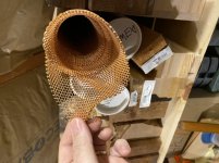
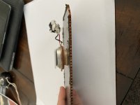
This is my opinion based on my experience with NOMEX soundboards. I am not an engineer. So, follow my advise at your own peril. The photos are of a roll of NOMEX and how NXT used it in and exceedingly lightweight panel.
KEVLAR honeycomb is very heavy(dense) compared to aramid honeycomb or NOMEX
In my understanding the goal is an very light ( low density ) panel that has high stiffness compared to its density. That is why FOAMULAR 150 works well. To me it makes little sense to take a Nomex core and put two layers of high density Woven carbon fiber on the core. To my reasoning a composite with Nomex should have a very light weight skin such as wood veneer or mylar(thanks Burnt).
This is my opinion based on my experience with NOMEX soundboards. I am not an engineer. So, follow my advise at your own peril. The photos are of a roll of NOMEX and how NXT used it in and exceedingly lightweight panel.
KEVLAR honeycomb is very heavy(dense) compared to aramid honeycomb or NOMEX
Attachments


Last edited:
For us Brits, there's this supplier as well:
https://www.easycomposites.co.uk/#!...ycomb/3mm-29kg-aerospace-nomex-honeycomb.html
Regards,
Ian
https://www.easycomposites.co.uk/#!...ycomb/3mm-29kg-aerospace-nomex-honeycomb.html
Regards,
Ian
Thanks for the clarifications, I managed to find aramid honeycomb locally although they don't specifically call it nomex.
Wood veneer is also fairly easy to find, but the prices vary quite a bit.
Mylar would be far cheaper from what i can tell, I cant help but wonder if the Podium engineer ever experimented with thin wood veneer (or any other material), but decided to go with a much cheaper but slightly inferior option for price concerns. Perhaps Mylar is the perfect coat, and it wasn't a compromise at all. Any guesses?
Why do we, when building DMLs put our drivers on points where most nodes exist?
Frankly, I doubt few of us actually know where the most nodes actually are.
Some put the exciters at the 2/5 (0.4) position because the Parts Express guy said to, or the Tech Talk guy said to, but beyond that don't even know what nodes and anti-nodes are.
Some may know what nodes and antinodes are, and put their exciters at the 0.4 position because they think that's where the most nodes are, and others because that's where they think the most anti-nodes are. But what they believe to be true doesn't actually matter, so either way it's the same.
The Azima patents actually refers to the fractions 3/7 (.428) and 4/9 (0.444) and 5/13 (0.385). My guess is that the Parts Express guy decided those all seemed close enough to 0.4 so went with that.
But it's pretty clear that Azima's idea was that the exciter should be placed at the spot that excited the greatest number of modes (i.e. standing waves):
From the patent US 6904154B2:
A successful method and means for preferred transducer site identification resulted from finding those positions at which the number of dead spots for any of the resonant modes concerned is low or least and/or the number of vibrationally active resonance anti-nodes concerned is high or highest
It also should be noted that the location of the nodes and anti-nodes is highly dependent on how exactly the panel is supported. Free all around? Foam all around? Foam on the short edges only? Foam on the long edges only? Other? Interestingly, the Azima patents don't clearly (as far as I can tell) indicate what boundary conditions their favorite fractions actually apply to.
I suggest forgetting about the magic fractions. Measure your panels with the exciters in various positions in the vicinity of the center and see which gives the best response.
Eric
In my understanding the goal is an very light ( low density ) panel that has high stiffness compared to its density. That is why FOAMULAR 150 works well. To me it makes little sense to take a Nomex core and put two layers of high density Woven carbon fiber on the core. To my reasoning a composite with Nomex should have a very light weight skin such as wood veneer or mylar(thanks Burnt).
Dave,
You are mostly right here. But not regarding the woven carbon fiber skins vs. wood veneer. You are correct that carbon fiber is heavier (denser) than wood, between about 2 and 3 times, in fact. But carbon fiber composite is way stiffer than wood, something like 10 times. So you can actually make a lighter/stiffer panel using thin skins of carbon fiber on a core than you can using wood veneer on the same core.
That said, I think the wood veneer on honeycomb core is a pretty good idea, and much easier and cheaper for most hobbyists.
Eric
I suggest forgetting about the magic fractions. Measure your panels with the exciters in various positions in the vicinity of the center and see which gives the best response.
Eric
This method works really well. The differences in frequency balance with each position are pretty obvious.
Burnt
Please bear with me on this thought process.
Assuming the same NOMEX core dimensions for a panel with different skin materials...
Properties
Balsa 150 kg/m^3. 3.7 GPa
Spruce 430 kg/m^3. 10 GPa
Uni CF. 1550 kg/m^3. 181 GPa
Assuming all else is equal with the panel skins...
CF weight = 3 x spruce = approx 10 x balsa
CF stiffness = 18 x spruce = 45 x balsa
I found some woven CF cloth. 2 oz per yard (.004”)
Weight of this CF for a 2 x 4 ft panel both sides
10 oz ( not including epoxy)
Obviously, spruce or balsa in .004” would not be practical but would weigh 3 oz on spruce and and 1 oz in balsa.
Carbon fiber all else being the same would give the stiffest panel but would weigh more than the spruce and balsa.
So, from an acoustic point of view assuming same vibrator, same panel size with same NOMEX core, what is more important- total panel weight or panel stiffness
I also understand that different materials have different surface radiation coefficients. How does that figure into material selection for panel skins?
Sorry if this is rambling. I am trying to sort this out for material selection. Cost is also a big issue.
Hi davelang,
I have posted a quote from Paul Burton the original designer/developer of the Podium system, I had nothing to do with them, I should be so lucky!
If you click on the link at the top of the post "Podium Sound planars", in blue, it will take you to the original thread. Sorry If I confused you.
I do know a little bit about the Podium panel material, I am interested in making a variant myself.The outer skin of the Podium is a thin MYLAR film, or PET as the generic material. It can be adhered to a Nomex honeycomb using Araladite. However, you may have a better solution to hand with the material used for guitar tops. Nomex honeycomb combined with a thin ply skin could be very good-its the direction I am looking to. If you have made guitars you already know how to laminate them but I make a few suggestions below.
This is a UK source for thin Finnish birch ply which you can get as thin as 0.4mm !
Thin Finnish Birch | Birch Plywood Panels | Latham Timber
I expect you will be able to get a US source as well.
If you want to try the MYLAR route this is a supplier
Mylar Rolls : TAP Plastics
On the lamination process I plan to do the following. I have built large ESL's using a variation on this method and it works quite well.
1) Use slow setting Araldite - there is no need to use the fast setting stuff it will just rush the assembly process
2) Stretch the MYLAR film out over an MDF panel and tape it down to remove wrinkles.
3) Using a roller, roll the Araldite onto one side of the NOMEX Honeycomb
4) Lower the honeycomb onto the MYLAR film
5) Place a second MDF sheet on top of the NOMEX honeycomb.
6) Leave the assembly until the Araldite has set completely- at least 12 hours- you will be stressing the skin when you flip the NOMEX/MYLAR assembly over and you must have a complete bond before doing so
7) When the Araldite has set, move the assembly to one side while you prepare the MYLAR sheet for the second skin.
Repeat the process above for the second side.
If you are making big panels I would suggest you get help from a friend as handling large sheets of NOMEX covered in glue is going to be tricky.
Don't worry about using a bit too much Araldite, it will add relatively little mass and and excess will form beads between the MYLAR film and the NOMEX core- this is a good thing.
CAPS used for clarity, not for shouting I promise!
I hope that helps
Burnt
Here in the States, you can find NOMEX honeycomb fairly cheap at Amazon...its sold in smaller sheets as car radiator material in like 20" x 30" sheets for like $30... and I see you can even buy it in huge 40" by 100" sheets...: Amazon.com: nomex honeycomb
geo
Frankly, I doubt few of us actually know where the most nodes actually are.
Some put the exciters at the 2/5 (0.4) position because the Parts Express guy said to, or the Tech Talk guy said to, but beyond that don't even know what nodes and anti-nodes are.
Some may know what nodes and antinodes are, and put their exciters at the 0.4 position because they think that's where the most nodes are, and others because that's where they think the most anti-nodes are. But what they believe to be true doesn't actually matter, so either way it's the same.
The Azima patents actually refers to the fractions 3/7 (.428) and 4/9 (0.444) and 5/13 (0.385). My guess is that the Parts Express guy decided those all seemed close enough to 0.4 so went with that.
But it's pretty clear that Azima's idea was that the exciter should be placed at the spot that excited the greatest number of modes (i.e. standing waves):
From the patent US 6904154B2:
A successful method and means for preferred transducer site identification resulted from finding those positions at which the number of dead spots for any of the resonant modes concerned is low or least and/or the number of vibrationally active resonance anti-nodes concerned is high or highest
It also should be noted that the location of the nodes and anti-nodes is highly dependent on how exactly the panel is supported. Free all around? Foam all around? Foam on the short edges only? Foam on the long edges only? Other? Interestingly, the Azima patents don't clearly (as far as I can tell) indicate what boundary conditions their favorite fractions actually apply to.
I suggest forgetting about the magic fractions. Measure your panels with the exciters in various positions in the vicinity of the center and see which gives the best response.
Eric
Agreed on measuring/listening to the exciters while moving it around the panel surface to see where it sounds best/loudest, my only caveat is to do it after the panel has already been framed/mounted. That way you are assured of getting the right points, before playing with any damping, etc...
What I'm not sure of is if using multiple exciters will the points change? I.e., you find the perfect spot for one exciter, will that still be perfect spot for 2 or more excitors on the same panel...various theory seems to say keep multiple exciters closer together, other theory says use the NXT spots and then continue to sub-section the panel to find the next best using the same ratios...which is what the TI guys kind of did when they added the weights originally for damping in their first vid. But it all may not matter, I know some say they can't really hear that much of a difference when moving the exciter around the panel and others found they could and settled on like 1/3,2/3 positions (similar to 2/5,3/5 or NXT's "golden and silver ratios" already mentioned. Of course then you have the podiums which simply just seemed to like them down the middle equally spaced and others have tried the same but slight off-center and still others have tried very specifically spaced for special DML needs (all of this can be found in the 3 or so main DML threads we've all seen for the past decade plus). Another example is the one NXT patent recently posted where they show the panel being hung and the exciter place all the way down in one bottom corner of the panel...go figure...
I'm almost at the point to say that exciter position may not even be all that import/critical in the end and the shape/size of the panel may play an even bigger role in its "sound". But hey, thats why we are all here right...to experiment and try to get some answers
")
geo
Please, this is just a thought/question, with no scientific reasoning, as I am no physics professor.
Why do we think that a laminate is the best solution for our DML panels/diaphragms? Surely/possibly, the added internal structures complicate the distribution of the vibration modes within the panel? Wouldn't the vibrations be 'purer' if the panel was composed of the one material with as little internal/external construction as possible?
Why do we think that a laminate is the best solution for our DML panels/diaphragms? Surely/possibly, the added internal structures complicate the distribution of the vibration modes within the panel? Wouldn't the vibrations be 'purer' if the panel was composed of the one material with as little internal/external construction as possible?
- Home
- Loudspeakers
- Full Range
- A Study of DMLs as a Full Range Speaker