Cheapvega.
I'm away for a few days and maybe I've had a glass of wine too many, but I don't recognize the response results.
There seems to be huge dips in the response at the 2k and4 k with slopes leading to and from these ?
I'm starting to wonder about the exciter?
You seem to be getting a stronger out put below about 400hz with these excites but a weaker output above this ?
If you are using 20db of boost and still not getting a good result ,this seems to say to me ,something is wrong ?
Maybe measuring the exciters flat disc foot could be interesting? What is the real output of this exciter ?
Maybe putting the exciter on a known panel material such as 3mm ply could help to understand the response ?
Steve.
I think the exciter def isn't ideal. I am going to have to sacrifice some efficiency to get a good response. I have a GRS planar tweeter sitting around. I will see how that does off axis. I might end up using the DMLs up to 1-2K or so and then using the planars as mids + tweeters. Asking 1 driver to cover full range is a dream but it's also asking a lot.
Hi Cheapvega,@spedge all measurements had the mic basically 2-3cm in front of the exciters. I was more just trying to see the speaker's natural response and seeing how much EQ could affect that. I will do a full measurement + EQ from listening positions once these are installed.
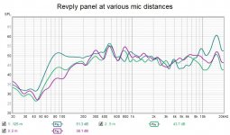
I got some more measurements, now with the exciters screwed directly to the panel rather than stuck with squishy double edged tape. I tried 2cm (yellow), 20cm (blue) and 1m(green). There are def some room interactions at distance, but again I am not testing in a similar room or for room interactions. Just seeing what the driver can do.
View attachment 1016276
After some eyeball EQing I got the following at 20cm (red vs raw in blue):
View attachment 1016277
Still definitely some tweaking to do, and the filters to fix the high end were heavy. There is a serious hole at 12K; there is a good 20dB of boost there and there is still a bit of a hole. But music sounds much better now and I can see where I need to tweak to get things flat.
That is all kind of secondary though. The main takeaway for me is these things can legitimately cover the full range, only needing a subwoofer to fill in the lowest of the low end. There is still a little "distance" and coldness in the sound, but I think some of that is from the holes at ~500 and ~3500 (the latter also being a weird hole). But it's all tunable.
Next step is to get my TPA3255 chip and ADAU1701 wired up so I can see how these run with more headroom. Gonna go ahead and order 4 panels for my kitchen. I'm sold.
some comments / question
- the raw frequency response shows high level differences, 20dB. This could lead to power problem while EQing no?
- now the exciter is screwed, the loss of level as the frequency increases seems starting at a lower frequency than when gluing. An effect of the screw weight?
- Which ADAAU1701 card do you use? (I would like to choose an EQ solution for my system)
In my experience, placing the mic very close to the panel can give very useful, or very misleading, information. Be wary. For conventional speakers, close mic-ing can help mitigate room effects. But for panel speakers, I think the situation is more complicated. There are at least two issues I think everyone should be aware of when close mic-ing panel speakers.
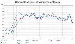
The first is that it unrealistically increases the low frequency response. For example, attached are measurements I made on two panels at 125 mm, 500 mm and 2000 mm for two different panels. One is "Revply" plywood, and the other has carbon fiber skins on a balsa core. Both panels are about 400 mm x 600 mm attached to a frame with foam around the perimeter. In both cases, the response at frequencies below about 300 Hz if relatively much higher at 125 mm than it is at 2000 mm. I'm still not certain myself, but I suspect the reduction at lower frequencies is a "coincidence frequency (CF)" effect. The CF of these panels is actually about an order of magnitude higher (3000 Hz vs 300 Hz), so that confuses me, but maybe it takes an order of magnitude before the effect becomes obvious. The carbon panel has a lower CF than the plywood, and seems to begin dropping off at a bit lower frequency that the plywood, so at least that makes sense.
more to come....
Eric
Attachments
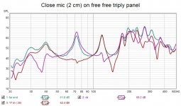
The second issue is that a close mic essentially acts as an accelerometer, which indicates the extent of movement of the panel at a particular spot, but doesn't necessarily indicate the effective radiation of sound power. That is, it basically tells you how much the panel is actually moving at that spot on the panel, but it doesn't necessarily tell you if that motion actually creates sound in the far field. As I have recently begun to understand, close mic-ing can provide really very useful information when you want to study the modal behavior of the panel, and/or determine the panels base properties (i.e. bending stiffness, elastic moduli, etc). But I'm really wary of it as an indicator of a panel's overall performance. The figure attached is an extreme example. This is a 300 mm x 1200 mm plywood panel hung horizontally by strings, with the exciter mounted at one end of the panel (I said it was extreme!). All thee measurements are about 2 cm from the panel face at different places along the length of the panel at the center of the panel's width.
One measurement is at the far end of the panel. This one shows the most resonances, since many modes have high displacement (motion) there. Another measurement is at the center (ctr) of the panel. This shows a lot of resonances too, but some are notably missing, at about 117 Hz, for example. The reason is that the mode that vibrates at 117 Hz has a node at the center, and hence no motion. The third measurement is at 0.36 of the panel length from the panel end. This also shows a lot of resonances, but lacks a peak at 72 hz. Again, the reason is that the mode that vibrates at 72 Hz has a node (no motion) at that location.
The bottom line is this: the measured response with the mic very close to the panel reflects very well the displacement/motion of the panel at that particular location, but perhaps not the actual far field response of the panel.
Eric
Attachments
1. This is a question I have. I'll elaborate more below. But my short answer is... I don't know lol.Hi Cheapvega,
some comments / question
Christian
- the raw frequency response shows high level differences, 20dB. This could lead to power problem while EQing no?
- now the exciter is screwed, the loss of level as the frequency increases seems starting at a lower frequency than when gluing. An effect of the screw weight?
- Which ADAAU1701 card do you use? (I would like to choose an EQ solution for my system)
2. I will have to really look back and forth between the screw and sticker mounting charts to see what is what there. But the high end responses seem similar- slight bump at 9k, then a big drop off from there with a hole at 12k.
3. ADAU1701 isn't in use in these tests; right now I'm using the DSP in the ZOUDIO.
I did some more testing.
I played with the planars and the panel some more today. The planars are a non starter- too much off axis variation. They are way more efficient than the panel. I crossed them over at 1.5k and still had to drop them down by about ~9dB for an even response. But that was directly on axis. I think they are closer off axis. So they would have hot spots in the room which I don't want.
Anyway I was able to get a response from the panel alone that was +3db across 70-17kHz. But that basically required a 25dB boost from ~12kHz and up.
Again I have the watts to pump this response to the volumes I want. But it's def at a cost, to the point that I'm wondering if the response is meaningless... what does this chart mean? (It's distortion)
The ZOUDIO I'm using is low on watts, even bridged, so I'm basically having to crank it to get useful readings. My TPA3255 has more watts, but I'm afraid I'm going to fry something with the kind of equalization I need for that response:
At a real loss. Music doesn't sound bad on it, but it's definitely audibly inefficient compared to that planar (rated at 94dB from 2.83V/1m). Just trying to think what the negatives are in the context of having enough watts.
Eric,In my experience, placing the mic very close to the panel can give very useful, or very misleading, information. Be wary. For conventional speakers, close mic-ing can help mitigate room effects. But for panel speakers, I think the situation is more complicated. There are at least two issues I think everyone should be aware of when close mic-ing panel speakers.
The first is that it unrealistically increases the low frequency response. For example, attached are measurements I made on two panels at 125 mm, 500 mm and 2000 mm for two different panels. One is "Revply" plywood, and the other has carbon fiber skins on a balsa core. Both panels are about 400 mm x 600 mm attached to a frame with foam around the perimeter. In both cases, the response at frequencies below about 300 Hz if relatively much higher at 125 mm than it is at 2000 mm. I'm still not certain myself, but I suspect the reduction at lower frequencies is a "coincidence frequency (CF)" effect. The CF of these panels is actually about an order of magnitude higher (3000 Hz vs 300 Hz), so that confuses me, but maybe it takes an order of magnitude before the effect becomes obvious. The carbon panel has a lower CF than the plywood, and seems to begin dropping off at a bit lower frequency that the plywood, so at least that makes sense.
more to come....
Eric
You are right. The good approach is always to be careful with measurements mainly in acoustics where many complex phenomena occur.
My proposal to have a look to the close proximity measurements comes from my little experience (4 type of panels experimented) I found quite good similarities with distant measurements. Much better than cone loudspeakers. For sure some frequency ranges are more impacted than others.
You have identified one in the bass. The panel in the room won't reach the proximity measurement. So the qualification of "best performance". Maybe wrong?... but without EQ, the panels we appreciate are the ones with the "flattest" close proximity response.
Some bumps in the medium appear also.
And the upper range also...
That's a lot? Considering the dispersion of such measures linked to the mic position... perhaps not.
About the loss of level in the bass my interpretation is in the room interaction... I don't understand the mechanism but I found some evidences (at least i interpret that as evidences) doing outdoor measurements with my plywood panel. In those conditions, the panel at distance (2m) reaches the very nearly the bass level that is seen at proximity. If the reason was the coincidence frequency, the effect would have been present also outdoor.
In the medium I suspect also interactions like the rear wall (see in previous post) and, to be proofed, panel edge effect (lower than for an OB). Here also the mechanism is not clear for me.
Christian
Hmm... My knowledge in acoustic is too short to comment what the pressure measured by the mic reflects. As mentionned in the previous post, I just put in regard close proximity measurement at the axis with distant one and found enough similarities in conjonction with our listening opinion of the panels. From your test, what about to say if a mode is not present at the exciter it won't be present elsewhere (this leads to appreciate the straightness at proximity?). Hmm...The second issue is that a close mic essentially acts as an accelerometer, which indicates the extent of movement of the panel at a particular spot, but doesn't necessarily indicate the effective radiation of sound power. That is, it basically tells you how much the panel is actually moving at that spot on the panel, but it doesn't necessarily tell you if that motion actually creates sound in the far field. As I have recently begun to understand, close mic-ing can provide really very useful information when you want to study the modal behavior of the panel, and/or determine the panels base properties (i.e. bending stiffness, elastic moduli, etc). But I'm really wary of it as an indicator of a panel's overall performance. The figure attached is an extreme example. This is a 300 mm x 1200 mm plywood panel hung horizontally by strings, with the exciter mounted at one end of the panel (I said it was extreme!). All thee measurements are about 2 cm from the panel face at different places along the length of the panel at the center of the panel's width.
One measurement is at the far end of the panel. This one shows the most resonances, since many modes have high displacement (motion) there. Another measurement is at the center (ctr) of the panel. This shows a lot of resonances too, but some are notably missing, at about 117 Hz, for example. The reason is that the mode that vibrates at 117 Hz has a node at the center, and hence no motion. The third measurement is at 0.36 of the panel length from the panel end. This also shows a lot of resonances, but lacks a peak at 72 hz. Again, the reason is that the mode that vibrates at 72 Hz has a node (no motion) at that location.
The bottom line is this: the measured response with the mic very close to the panel reflects very well the displacement/motion of the panel at that particular location, but perhaps not the actual far field response of the panel.
Eric
Christian
ChristianHello Toddincado,
To be sure to follow you : the left panel of the picture here below is what gives you satisfaction? So the plywood working around the exciter and then the EPS.
Would you remind the dimensions of your panel, its thickness? Just to add some information in an update of the history file I already posted.
Your solution to attached the exciter is interesting. Not so easy to keep it straight, with no effort from the cable neither effort on the voice coil.
About your listening feedback, I could make about the same comment : it is on the vocals we detect the defects while having a very good sound (probably not necessary the exact one but the one we like) on instruments. Is the panel coloration good for instruments not for the voice?
Christian
View attachment 1015293
"The left panel of the picture here below is what gives you satisfaction?" Yes. Removing the bulk of the EPS from the back of the wood made the sound of vocals much better. I will be replacing the plywood with better wood as soon as I can get my hands on some. I hope to obtain some birch panels or salvage wood from old broken guitars and make slightly larger "flower" shapes to replace the current "t" shapes.
"Not so easy to keep it straight, with no effort from the cable neither effort on the voice coil." I'm not exactly sure what you're asking here but I'm a believer in taking as much weight off the exciter as possible by using a "spine" of whatever design. Seems to me as though this would help with accuracy and tightness as well over a "free floating" panel.
"Is the panel coloration good for instruments not for the voice?" Yes, the coloration is better for instruments which is why I will replace the cheap plywood with real wood as mentioned above in search for the best of both worlds. I'm not going to kill myself searching for perfection as I use these as supplemental speakers to help fill my small space with larger, smoother sound than I can achieve with my bookshelfs and sub alone, and believe me, they already achieve that!
Panel is super dense EPS averaging 3/8" (9.5 mm) in thickness, 17" (43.2 cm) height x 13 1/2" (34.30 cm) at widest point. The wood is 7"x7" (17.8 cm) tip to tip. I sanded the EPS panel down thinner toward the exciter placement point making the entire front of the panel slightly concave using 50/50 glue/water on front and back of EPS, wood is bare on back while front is painted thinly with black acrylic paint.
Cheapvega,1. This is a question I have. I'll elaborate more below. But my short answer is... I don't know lol.
2. I will have to really look back and forth between the screw and sticker mounting charts to see what is what there. But the high end responses seem similar- slight bump at 9k, then a big drop off from there with a hole at 12k.
3. ADAU1701 isn't in use in these tests; right now I'm using the DSP in the ZOUDIO.
I did some more testing...
About efficiency, this is for sure a strong point of panels especially with dense material. This explain the research for light material stiff enough.
Your observation about the planars directivity is also one reason to persevere even if the way is a bit difficult.
I don't know what to say about your distortion graph (what is what? the y axis is no more dB? which level was it?) but for sure I would say you have a risk to fry something with a low efficiency material, a deep EQing. Do you listen loud?
Christian
I will keep watching the research of others on light + stiff material. The y axis of the distortion graph is % distortion so the first fundamental is distorted by 100% in the sweep. That sounds like it can't be right.Cheapvega,
About efficiency, this is for sure a strong point of panels especially with dense material. This explain the research for light material stiff enough.
Your observation about the planars directivity is also one reason to persevere even if the way is a bit difficult.
I don't know what to say about your distortion graph (what is what? the y axis is no more dB? which level was it?) but for sure I would say you have a risk to fry something with a low efficiency material, a deep EQing. Do you listen loud?
Christian
I don't listen too loud. System is in my kitchen where my family spends a lot of time, so it's mainly background noise at moderate levels. When I'm home alone I turn it up a little bit but nothing crazy. It should be fine.... I have 12 exciters, so I might order another 4 to have 80W RMS/ch @ 4 ohms. That will be plenty for my listening levels, even with the crazy EQ.
The first fundamental is the primary signal, it's supposed to 100% in this view. The black squiggly line below it is the one to look at. That's the total harmonic distortion (THD). THD is basically the sum of everything other than the primary (i.e. fundamental) signal. I can't say exactly what's considered "good" in audiophile circles, but I like to see 5% or less for my dml panels over most of the range I intend to use the panel for. You are getting 10%, which is a bit higher than I prefer, but not horrible. Also, as Christian has alluded, THD generally increases when you crank up the volume.The y axis of the distortion graph is % distortion so the first fundamental is distorted by 100% in the sweep. That sounds like it can't be right.
Usually, when I see distortion plots, I see them plotted with the Y axis in SPL instead of %. There are some like that in the original post of this thread, in fact. On that scale, look for close to 30 dB difference between the fundamental and the THD, which corresponds to about 3% THD.
Eric
Christian,Hmm... My knowledge in acoustic is too short to comment what the pressure measured by the mic reflects. As mentionned in the previous post, I just put in regard close proximity measurement at the axis with distant one and found enough similarities in conjonction with our listening opinion of the panels. From your test, what about to say if a mode is not present at the exciter it won't be present elsewhere (this leads to appreciate the straightness at proximity?). Hmm...
Christian
Have a look here:
https://www.comsol.com/multiphysics/eigenfrequency-analysis
and scroll down about 2/3 of the way to the section on "Plates".
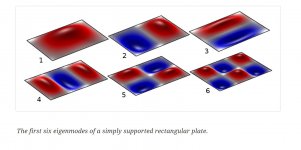
Consider mode 1 compared to mode 2. In mode 2, the portion in blue is always 180 degrees out of phase with the portion in red. If you measure with a close mic in the center of the red or blue sections, you will measure a strong response at the frequency corresponding to this mode. But if you put the mic in proximity to the grey area between the red and blue, you will measure no response at that frequency. Also, if you measure at a distance (say >1 m), then the response from the red and blue areas (which are out of phase) will cancel each other, and again, you get no response.
On the other hand, for mode 1, there is no corresponding blue area to cancel the red area out. hence, in the nearfield (and far-field), this mode will produce a significant output.
As you go to higher and higher frequencies, there are more modes like mode 2, for which there are red and blue areas that cancel each other in the far field. But thankfully, there are also other modes like mode 1, where there are more red areas than blue, and hence don't cancel each other out. These are the modes that really contribute to the far-field response.
When you close mic, you arbitrarily choose a position on the plate which combines the response of some modes like mode 1 (that contribute in the far-field) and other modes (like mode 2) that do not.
Eric
Attachments
I knew you would say that! I disagree, but I also acknowledge that you could be correct! I have not tried outdoor measurements,About the loss of level in the bass my interpretation is in the room interaction... I don't understand the mechanism but I found some evidences (at least i interpret that as evidences) doing outdoor measurements with my plywood panel.
Christian
Eric
for many, many years now ,I have been saying that single point response measurements are basically a waste of time when measuring a dml panel.The second issue is that a close mic essentially acts as an accelerometer, which indicates the extent of movement of the panel at a particular spot, but doesn't necessarily indicate the effective radiation of sound power. That is, it basically tells you how much the panel is actually moving at that spot on the panel, but it doesn't necessarily tell you if that motion actually creates sound in the far field. As I have recently begun to understand, close mic-ing can provide really very useful information when you want to study the modal behavior of the panel, and/or determine the panels base properties (i.e. bending stiffness, elastic moduli, etc). But I'm really wary of it as an indicator of a panel's overall performance. The figure attached is an extreme example. This is a 300 mm x 1200 mm plywood panel hung horizontally by strings, with the exciter mounted at one end of the panel (I said it was extreme!). All thee measurements are about 2 cm from the panel face at different places along the length of the panel at the center of the panel's width.
One measurement is at the far end of the panel. This one shows the most resonances, since many modes have high displacement (motion) there. Another measurement is at the center (ctr) of the panel. This shows a lot of resonances too, but some are notably missing, at about 117 Hz, for example. The reason is that the mode that vibrates at 117 Hz has a node at the center, and hence no motion. The third measurement is at 0.36 of the panel length from the panel end. This also shows a lot of resonances, but lacks a peak at 72 hz. Again, the reason is that the mode that vibrates at 72 Hz has a node (no motion) at that location.
The bottom line is this: the measured response with the mic very close to the panel reflects very well the displacement/motion of the panel at that particular location, but perhaps not the actual far field response of the panel.
Eric
When I measured a panel similar to burntcoils blonds panel, tall and slim, with the exciter at one end of the panel ,I measured the top half and bottom half separately, and took peak hold measurements by moving the microphone around the whole of the panel surface.
I also took in room responses using the same principles, where my listening position is.
We need to know what the panel is putting out into the room and what the room is doing to that sound it is putting out.
I found this interesting ,as it made a difference to the panel response, depending on which way up the panel was standing(testing on the floor)
Anyway, moving the microphone around the surface at say 1cm will show the positive and negative swings of the panel and the phases inbetween.
There have been many pictures showing the chaotic nature of dml panels(which they are not as they can be predicted).
What these pictures show to me is that about 50% of the back of a panel is out of phase with itself and at varying points inbetween these peaks.
And is mirrored on the front side, so the front side is approx 50% OUT and IN phase with the near side and at varying points inbetween !!
so one random point measurement at any one position would not make any sense.
But as for the measurement in front of the coil area , this is useful as it helps to see the exciter pistonic output into the panel.
I think of the exciter area as full range tweeter, but obviously as you pull further away from the panel this area will not drive the room down in the low end,hence the fall off.
But you should not just take a single point measurement of the centre area at 1cm , as this will also change considerably from one fraction of a cm to the next because of the coil and cavity resonances and oil can affect.
these problems I have also banged on about over the years which also seem to be ignored.
this forum could be an answer for the coil area but I think my fabric type dome at least on thin materials , may be a better answer ?
https://www.diyaudio.com/community/threads/phase-plug.192215/
I look forward discussions on these problems as they need to be sorted out and clarified.
Steve.
Thanks for the explanation. I isolated the THD. Mostly below 10%... I think that is decent considering the circumstances. The amp I will run has more headroom so there should be less distortion in the end.The first fundamental is the primary signal, it's supposed to 100% in this view. The black squiggly line below it is the one to look at. That's the total harmonic distortion (THD). THD is basically the sum of everything other than the primary (i.e. fundamental) signal. I can't say exactly what's considered "good" in audiophile circles, but I like to see 5% or less for my dml panels over most of the range I intend to use the panel for. You are getting 10%, which is a bit higher than I prefer, but not horrible. Also, as Christian has alluded, THD generally increases when you crank up the volume.
Usually, when I see distortion plots, I see them plotted with the Y axis in SPL instead of %. There are some like that in the original post of this thread, in fact. On that scale, look for close to 30 dB difference between the fundamental and the THD, which corresponds to about 3% THD.
Eric
Thank you Eric for the link. It is a very good source.Christian,
Have a look here:
https://www.comsol.com/multiphysics/eigenfrequency-analysis
and scroll down about 2/3 of the way to the section on "Plates".
...
When you close mic, you arbitrarily choose a position on the plate which combines the response of some modes like mode 1 (that contribute in the far-field) and other modes (like mode 2) that do not.
Eric
In the "Plate" section they give the formula of the Eigenfrequencies for a free edge plate. Some weeks ago I started to dig around it to see if there is something to see around the a/b ratio. It leads now to a new idea to superimpose the estimated Eigenfrequencies with a panel frequency response (FR). By exporting the FR from REW to a Python script, it should do the job.
Do you think the edge conditions of our panels are close enough of the free conditions?
I have somewhere a paper showing how the Eigenfrequencies change with the condition. In a first look I found it a bit difficult...
Does the couple (m,n) start at (1,0), (0,1)?
If I follow you analysis... for example among the first modes shown, only the number 1 and 4 give a pressure at distance? Meaning that many modes are useless? Hmm (again a "Hmm"...
") ). Sorry I am not at ease with the modal model of the DML! But sure I am working on!
). Sorry I am not at ease with the modal model of the DML! But sure I am working on!Christian
No problem Eric. Let's see what further exchanges and experiments will give.I knew you would say that! I disagree, but I also acknowledge that you could be correct! I have not tried outdoor measurements,
Eric
Searching about the Eigenfrequencies in my documents, I found a paper from NXT I have certainly not read carefully enough, I found that about low frequencies (see extract below)
OK it says also that single point measure doesn't fully reflect the perceived response... This a chance for pink noise measurements or FFT on IR without window in a living room.
OK again, the next chapter introduces the notion of "diffuse dipole" to explain (to model?) how the sound radiates and how the front and the rear interact. To far of what I can understand for now... or over condensing for my understanding.
Stevefor many, many years now ,I have been saying that single point response measurements are basically a waste of time when measuring a dml panel.
...
I look forward discussions on these problems as they need to be sorted out and clarified.
Steve.
As I am writing here, I have 2 panels playing in full range simply a TV show. For sure that works. In addition there is beauty in this apparent simplicity. A friend who understands little about technique and physics but who has a great artistic sense was seduced by this aspect.
To come back to the technical side, I think there is no difficulty to agree that it is the measures at the listening position that matter.
There is also no difficulty to agree that a space average over the listening area to reduce the effects linked to a specific position might help.
Compare to standard loudspeakers, the panel measurement at listening position is perhaps easier.
The other measurements are tentative for me to build my own representation, experience, of those speakers, to understand the origin of what we observe (see in other posts about the low frequency loss or the rear wall effect).
As you mention it is trials to understand what the panel outputs by itself, how it interact with the room.
It is in this way, while comparing measurements without referring to any model, I mentioned this possible correlation (probably already done by the past?) between a flat enough axis proximity response and a good sound without EQ. For sure it is not 100% true over the full range; specially at high frequencies where the wavelengths become close of the voice coil diameter.
I agree the number of panels built is low... 4 models... See it as an indicator.
As in science, any additional experience going in that way will increase the possibility for proximity measurement to be an indicator. A counter example of a panel with a "good sound" without EQ without a "good" proximity measurement will kill this indicator. The analysis of this example will give interesting information. No such example on my side for now.
To come to the model aspect, model in the meaning how we can built an intellectual representation of how the panels work, my neurons are divided in 2 representations (perhaps more!). The steady state (or frequency) representation based on the modes which is the one we found in most of the papers and the transient (or time) one based on the propagation of waves from the exciter, damped by the membrane material and reflected at the edges... And for now, they are not unified in my mind by a kind of upper understanding... Even when I was more deeply involved in electronic design, I was not really fan of the steady state or frequency approach, same when I designed audio amp. always preferring the transient, same in acoustics. Frequency is perhaps a too high level mathematical abstraction for me. So for now I see those pseudo-chaotic representation more as an intermediate element coming from a finite element computation than a full explanation. A step is missing... and I don't see the phase as the explanation. Sorry. It is intellectually challenging.
So as you said, let's try to sort out and clarified all of that.
The next step is to understand what is the right input to go forward.
To wait for that step, I put here also to be more clear in my answer to Eric the comparison of the response of my plywood panels in room (for practical reasons it was "only" 1.5m), outdoor same distance, proximity. All 1/6 octave filtering no windowing.
Let us the brain cool, it is late here now... working tomorrow!
Christian
- Home
- Loudspeakers
- Full Range
- A Study of DMLs as a Full Range Speaker