DML Canvas Testing
Hi everyone,
trying to update my test protocol on dml canvas panels and planning to do some testing in the upcoming weeks.
I ll have:
Canvasses: 4x Cotton (260g/m²; 4x primed): 2x 30*40cm & 2x 40*50cm
I ll measure each of the panels resonance frequency by using a drum tuning app and tapping on the canvas.
Exciters: 4x Dayton DAEX25FHE-4, one for each canvas panel, mounted centrally
Ply: Birch Plywood 2.5mm mounted centrally
Ply Dimensions: 9.2*13cm (small canvas frame) and 11.9*16.8cm (big canvas frame)
= 10% of canvas surface area; width < 4/5 height (source: Dayton) & ratio 1.41:1 (NXT technical notes)
Question: what might be a better orientation of the ply panel relative to the canvas panel? long sides parallel or perpendicular?
I want to do REW near-field frequency sweep measurements on both sides of the panels in the following succession
I: - one big & small canvas panel with ply (pva) centrally glued to canvas and exciter centrally glued to ply panel
- one big & small canvas panel without ply panel; just the exciter centrally glued to the canvas
II: only applicable for second pair of big & small canvas panels: glued ply panels to the canvas with appropriate exciter-diamteter cutouts
III: all panels: added beams of transparent silicone around all inner edges, and in form of a spiderweb (as suggested and later retracted? by Offgrid") )
)
IV: all panels: added spine
V: all panels: added layer(s) of dilluted pva
VI: all panels: added strips of FK foam on the back of the spine
VII: all panels: using a tone generator to identify when and at what frequency buzzing occurs
VIII: all panels: room impacts on frequency curve due to different panel to wall distances; parallel/unparallel mountings
Any feedback on what I should change? Any hypotheses I could try to look into?
Hi everyone,
trying to update my test protocol on dml canvas panels and planning to do some testing in the upcoming weeks.
I ll have:
Canvasses: 4x Cotton (260g/m²; 4x primed): 2x 30*40cm & 2x 40*50cm
I ll measure each of the panels resonance frequency by using a drum tuning app and tapping on the canvas.
Exciters: 4x Dayton DAEX25FHE-4, one for each canvas panel, mounted centrally
Ply: Birch Plywood 2.5mm mounted centrally
Ply Dimensions: 9.2*13cm (small canvas frame) and 11.9*16.8cm (big canvas frame)
= 10% of canvas surface area; width < 4/5 height (source: Dayton) & ratio 1.41:1 (NXT technical notes)
Question: what might be a better orientation of the ply panel relative to the canvas panel? long sides parallel or perpendicular?
I want to do REW near-field frequency sweep measurements on both sides of the panels in the following succession
I: - one big & small canvas panel with ply (pva) centrally glued to canvas and exciter centrally glued to ply panel
- one big & small canvas panel without ply panel; just the exciter centrally glued to the canvas
II: only applicable for second pair of big & small canvas panels: glued ply panels to the canvas with appropriate exciter-diamteter cutouts
III: all panels: added beams of transparent silicone around all inner edges, and in form of a spiderweb (as suggested and later retracted? by Offgrid
)IV: all panels: added spine
V: all panels: added layer(s) of dilluted pva
VI: all panels: added strips of FK foam on the back of the spine
VII: all panels: using a tone generator to identify when and at what frequency buzzing occurs
VIII: all panels: room impacts on frequency curve due to different panel to wall distances; parallel/unparallel mountings
Any feedback on what I should change? Any hypotheses I could try to look into?
That is really interesting and shows end grain balsa with no outer layer but also with the outer incisions.
The outer frame looks similar to the patent but we do not see how the rear side works.
Are these Gobel speakers actually any good? Has anyone heard them?
Actually, I'm sure the panel in the picture does have the outer layer. It's just that the outer layer in this case is fiberglass instead of carbon fiber. Apparently the original version was fiberglass, but now they have moved to carbon.
You might like this video. It even shows a pretty blonde making the panels!
Best of high end | Gobel high end loudspeaker manufacturer - YouTube
Hi everyone,
trying to update my test protocol on dml canvas panels and planning to do
II: only applicable for second pair of big & small canvas panels: glued ply panels to the canvas with appropriate exciter-diamteter cutouts
Bernardy,
Sounds like great fun!
What do you mean by "exciter diameter cutouts? Are you planning to glue the exciter directly to the canvas for those?
Thanks,
Eric
Hi Eric,
yes, copying Steve's (spedge) interesting experiment, I want to glue the exciter directly onto one small and one big canvas panel.
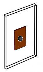
In a later step, I ll glue a ply panel onto the same canvas panels with cutouts for the already glued on exciters as in the following sketch... probably to see to what extent this step helps bringing back some of the lf?
Berny
yes, copying Steve's (spedge) interesting experiment, I want to glue the exciter directly onto one small and one big canvas panel.
In a later step, I ll glue a ply panel onto the same canvas panels with cutouts for the already glued on exciters as in the following sketch... probably to see to what extent this step helps bringing back some of the lf?
Berny
Attachments
Last edited:
.... Now check the comment paper which says:
Interestingly, at frequencies well below the critical frequency (10 214 Hz for the experimental DML), the far field so generated is omni-directional and the associated sound power per unit mean square force is independent of frequency and plate stiffness and inversely dependent on the square of the panel mass per unit area. The contribution of this source of sound, relative to that of the reverberant vibration field in the plate, increases with the plate loss factor.
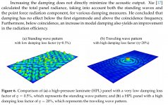
Control of the panel mechanical loss factor is vital, because the proportion of input power radiated by the reverberant component of panel vibration is crucially dependent upon the ratio of mechanical to radiation loss factor.
What this is saying is that since fc>>f0 the panel is acting not so much as a flexural resonator but as a panel piston speaker. In this case SPL is independent of frequency and depends ONLY on the panel mass per unit area which should be as low as possible for high SPL (desirable since the exciters are low power).
Hmmm. I must admit I don't quite get what the commenter (Fahy) is really trying to say here. But he doesn't actually say anything about the relationship of fc to f0 as far as I can tell. Anyway, for virtually any reasonable panel, fc is always much greater than fo. So if that makes a panel mainly pistonic, then every panel speaker is mainly pistonic. And I'm pretty sure that's not right.
I wonder if Fahy isn't really trying to get at how mechanical loss factor (presumably he means damping), changes the vibration field of the plate from standing waves to travelling waves, as depicted in the attached image from Zenker's paper. But both cases seem to me to be types of bending waves, rather than pistonic motion. No?
Eric
Attachments
It is very long thread. I want to build the canvas art panel made by Spedge and then remade successful by Jaxboy. But I couldn't find the latest best configuration of the art panel.
Could someone help me?
I have been away for the weekend in a remote cottage with no wifi,which was nice
,so sorry for the late reply.The art panel can be a pretty simple and easy panel to build .
If starting from scratch I would go for the basic 4x6inch balsa ply glued to the canvas as this would give you a full range panel to play around with, and give you an idea of what it can do.
You will be surprised.
I have made some recordings of this panel on this site, hopefully you have found them and listened ?
If you then wanted to make improvements , I personally would make a second panel and try out the improvements on that panel , which I would then compare with the basic panel, just to make sure it IS an improvement.
If you have any problems ,feel free to post them.
Steve.
Hi bernardy.
I'm not sure which interesting experiment you are talking about but if you are mounting an exciter on a canvas panel ,you will need a bracing support at the back to take the weight of the magnet.
Although the brace may not be necessary if the exciter is glued to a balsa panel.
The naked canvas panel should be good down to at least 300hz.
But with the balsa ply it should go down to about 40hz or so.
I'm not sure what is happening in you picture ? Are you cutting a large hole in the ply to slide over the exciter ?
As this would not drive the ply panel ?
Sorry if I've misunderstood the picture.
Steve.
Hi Steve,
if I remember correctly, you had the idea of attaching the exciter right onto the canvas without any plywood inbetween and found, that the canvas still performs well down to around 300Hz.
How would you compare the overall sound preformance between your favourite EPS board and the canvas-exciter combo?
Good point with the bracing support, thank you.
Yes, your interpretation of my pic is correct. But you get me thinking...
I dont know very much about the underlying physics of DMLs. You'd say, that sliding the plywood over the exciter doesn't make much sense from a mechanical standpoint?
Maybe I discard the sliding ply panels...
And look into the impact of a much higher plywood:canvas ratio like in this patent you once posted, Steve.
WO2019061685A1 - Full-frequency sounding structure of loudspeaker
- Google Patents
30*40cm canvas panel -> 6*8cm plywood panel?
And look into the impact of a much higher plywood:canvas ratio like in this patent you once posted, Steve.
WO2019061685A1 - Full-frequency sounding structure of loudspeaker
- Google Patents
30*40cm canvas panel -> 6*8cm plywood panel?
A back view of a manger drive unit.
I have heard these drivers in a large infinite battle ,I think it was an infinite battle ? Some years ago now.
It sounded like it was in a box , so I wasn't very impressed.
I'm not sure if it was out of the box it would have sounded that much better ?
A lot of damping and heavily enclosed.
Sorry photo will not load.
Steve.
Last edited:
A back view of a manger drive unit.
I have heard these drivers in a large infinite battle ,I think it was an infinite battle ? Some years ago now.
It sounded like it was in a box , so I wasn't very impressed.
I'm not sure if it was out of the box it would have sounded that much better ?
A lot of damping and heavily enclosed.
Sorry photo will not load.
Steve.
I see the Manger loudspeaker has the same openings with circles in the back as the Ondacustica CARLA Reference Nirvana....
I might have to try that. I just got some Dibond plates 3mm (0.3mm aluminium - 2,4mm polyethylene - 0,3mm aluminium) that I need to make something out of.
The holes in the back panel could be a way of controlling the sound pressure at the back of the panels.
This paper Redirect Notice seem to describe how to flatten the response in the lower frequency range, by closing off the back side around the edges and keep the area around the exciter open.
While the Manger s1 and Ondacustica Carla reference Nirvana have more openings at the edges, and smaller holes in the middle. Possibly to bring the resonance frequency up and control the response at a higher frequency range?
Glamesh.
From what I read in the gobel patent ,the output is restricted from the back above 4k to cover up the two massive peaks in their frequency plots.
I have spoken about these peaks many times and how to get around them when using coils to drive dml , or bending waves for that matter.
On light materials this sound will be pushed through the front as with cone speaket, not so much with hard materials.
Maybe it would have been better to design a panel that didn't have the peaks in the first place , rather than clamping and damping ?
As bending wave speakers have a different set of rules to dml , more in line with bmr , it is difficult to compare ?
They are a different bread.
Steve.
What is the coil and coil area, if not pistonic ?
This is the primary drive area . No ?
As I understand it "Pistonic" ideally means that the entire surface of the radiator (panel or cone) moves with the same amplitude, and in phase. In that case, displacement of the panel (say "z") is a function only of time, regardless of the position on the panel (x and y).
I suppose it's not completely wrong to stretch that definition to cover the case when perhaps most of the panel is moving in phase, even if the displacement amplitude varies greatly with position (as for a panel near or below its f0).
But it seems a big stretch to call the panel "pistonic" if only points in the area in the local vicinity of the voice coil are in phase with each other. If you pick a small enough area, that's true for any local area of the panel, be it the voice coil area or any other area.
I submit that for a panel to be considered pistonic, a pretty large, contiguous, portion of it ought to be at least in-phase, and ideally having similar amplitude.
Is that wrong thinking?
Eric
What this is saying is that since fc>>f0 the panel is acting not so much as a flexural resonator but as a panel piston speaker. I[/B]
But my main intention was not to debate the definition of "pistonic", but rather to question tsardoz's contention that since fc>>f0 the panel is acting not so much as a flexural resonator but as a panel piston speaker. .
I don't mean to pick on tsardoz, in fact I really to admire his resolve to understand and use math and physics to design a great speaker.
But as far as I know, most typical dml properties and panel dimensions result in an fc of at least 1000 Hz, and usually over 5000 Hz, and an fo of less than 500 Hz and usually less than 200 Hz.
So in that case, since fc>>f0, most every dml panel would be "pistonic", rather than a flexural resonator (i.e dml or bending wave speaker). If it was so, would we need this thread?
Eric
Last edited:
Glamesh.
As bending wave speakers have a different set of rules to dml , more in line with bmr , it is difficult to compare ?
They are a different bread.
Interesting. I always considered both "dml" and "bending wave" to be basically the same. Tectonics seem to agree:
Bending Wave Technology: An Audio Game Changer - Tectonic | Tectonic
A company called NXT was formed to research and commercialize this novel approach to loudspeaker design. In fact, 40 mathematicians, physicists and engineers buckled down to tackle the problem. Thanks to their work, the strong link between the size of a speaker and its bandwidth was finally broken by utilizing a complex arrangement of optimally spaced bending wave modes in a flat, composite panel to produce sound. In 2012, Tectonic Audio Labs acquired the rights to Distributed Mode Loudspeakers (DML) for sound reinforcement and has been producing loudspeakers with bending wave technology ever since.
What makes bending wave technology different is that in traditional speakers, pistonic (rigid body) vibrations of the cone diaphragm produce the sound. However, in Tectonic’s DML loudspeakers, the sound is produced by complex bending wave vibration patterns. Loudspeakers featuring this technology utilize bending waves excited into complex modal patterns to produce sound.
Sure, Gobel may want to distinguish his speakers from others, since they co$t so much. But I don't think the "rules" are really any different. Some just understand and execute them better than others.
Eric
- Home
- Loudspeakers
- Full Range
- A Study of DMLs as a Full Range Speaker