Hi
Attempting my first TL design. I have the HiWave 3.5" Full range drivers - specs in the attachment. I have a preliminary cabinet design per the attached SW dwg and the MJK Mathcad printout attached as well. I tried many iterations of sizing, stuffing etc trying to get a smooth spl curve. I don't really understand most of the data in the mathcad files, so I don't really know how to evaluate what I have done. Any comments, suggestions guidance are appreciated. Thanks.
Bob
Attachments
On a quick eyeball, it looks to me that the input into the worksheet is not what is drawn -you appear to have constant taper in the worksheet but the drawing indicates decreases in specific stages. The latter part of the sheet indicating the layout also appears to show an incorrect termini location relative to the drawing -high on the back rather than at the bottom of the front baffle.
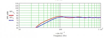
A point to note is that the BMR is already very inefficient, and a ruddy great shelving filter to compensate for step-loss will drop that to downright 'miserable' -well below 80dB. You would likely be better off doing without, and ramming them as far back against a wall as possible.
A point to note is that the BMR is already very inefficient, and a ruddy great shelving filter to compensate for step-loss will drop that to downright 'miserable' -well below 80dB. You would likely be better off doing without, and ramming them as far back against a wall as possible.
Last edited:
First Try
Scott - Thanks for the reply - I thought that the dimensions in the Lo sections (pg2) generated the attached profile and was how to model the taper. You are correct about Part 2 of the mathcad file - I didn't pay any attention to Part 2 at this point , but was just trying to get a flat response on the SPL curve on (pg5). Thought I could take it kind of a step at time trying to figure out how to use Mathcad and these calcs.

Scott - Thanks for the reply - I thought that the dimensions in the Lo sections (pg2) generated the attached profile and was how to model the taper. You are correct about Part 2 of the mathcad file - I didn't pay any attention to Part 2 at this point , but was just trying to get a flat response on the SPL curve on (pg5). Thought I could take it kind of a step at time trying to figure out how to use Mathcad and these calcs.
Attachments
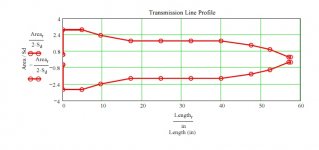
On a quick eyeball, it looks to me that the input into the worksheet is not what is drawn
Yeah, not even close, though don't know how much a correct one will alter the frequency response.
bknabe,
Plot your cab's acoustic path-length and you'll see that the bends 'balloon' out and when you get to the terminus it will be a flat plane with a hole in it like the driver/baffle's:http://www.diyaudio.com/forums/attachments/subwoofers/405769d1394763578-requesting-assistance-designing-isobaric-tapped-horn-th-tandem-drivers.jpg
WRT the simmed response, a T/S max flat tuning alignment is ~40 Hz, so yours appears a bit low, i.e. in general, when tuning so far below Fs the terminus's plot should be ~flat.
GM
Thanks for all the replies. Ok so here I have entered what I believe to be more or less correct data for parts 2 & 3 based on the drawing and where I have my existing R&L speakers in my room. If I change the drawing as shown, (since right now its easier than calculating all the sections) does the dwg pretty much represent the sim? So am I heading in the right direction or am I heading down a dead end??? Its very interesting trying to figure it all out, but quite daunting as the permutations are almost infinite. Thanks,
Bob
"Oh my must mean the same old place...You cant get there from here...."
Bob
"Oh my must mean the same old place...You cant get there from here...."
Attachments
You're welcome!
Much more so, though I don't recommend you build it this way unless it's physically larger since [1] acoustic efficiency is all about net box volume [Vb], so 'BIB' rules [bigger is better] and [2] the 'steps' help to decay its pipe harmonics, so less stuffing is required that otherwise reduces its fundamental acoustic efficiency. Good tutorial for the various resonant pipes: Resonances of open air columns
GM
- Status
- This old topic is closed. If you want to reopen this topic, contact a moderator using the "Report Post" button.
- Home
- Loudspeakers
- Full Range
- First try at TL design using MJKings mathcad files