I realize the L34 is an important resonance..
Neil,
I'm not sure exactly what you mean, but I don't think that there really is a resonance that is associated with the length of any particular segment independently. Rather, there is a set of resonances associated with the entire geometry.
Eric
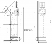
If that box is rectangular and that internal panel is parallel to the front and back panels, then S2a should be equal to S1
TBH, if I was doing this, I'd redesign the box a bit, rather than try to approximate it as-is in a Hornresp sim. For example, I'd lengthen that internal panel so it was equidistant from the top and the front, essentially making S2=S2a=S2b, and then adjust that chamfer in the back so that the CSA from the internal panel to the chamfer is equal to (S2+S3)/2. This are small changes that shouldn't change the box too much, but will make the sim of its response a bit more accurate.
BTW, make sure that you've set the value of "Path" in Hornresp to the distance between the center of the driver and the center of the vent.
Hi Brian,
I was accounting for the area of the vertical brace that is near the top of the closed end, near the woofer. That is why S1 is greater than S2A.
I was think that I would try extending the vertical baffle another inch higher, and try that. And I will check the distance to the chamfer panel in the back, to see it is in a "good" place - I am using this not necessarily for the inside function of the TL, but to both reduce the area of the top behind the dipole tweeter, and to reduce the higher frequencies from the back of the woofer tendency to reflect back out through the cone.
Thanks Brian for this very helpful input. And thanks Eric for checking the volume. I think that because of the "shoulder" at the step / corner at S4 / S4S, that some waves will be bounced back up, so to speak. And having that length to the step is possibly important to include. Though air will also transition into (and out of) the L45 segment, as well.
Oh, I am setting the path from the center of the opening to the center of the woofer; including the short slope along the cone.
Last edited:
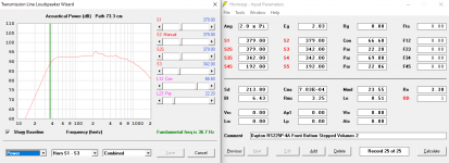
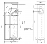
As usual your questions and suggestions have improved things! I extended the vertical baffle up 1" to make a more even transition down to the S3 section.
And I extended the brace all the way down to the horizontal baffle - because making S1 equal to S2a helped a bit. The brace is located 2/5ths from one side of the front baffle.
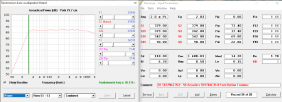
And I decreased the opening by 1/4" which lowered the fundamental frequency a bit and lowered the peaks a touch. The biggest peak at about 225Hz dropped by about a dB, and all the smaller peaks a ripples were smoothed, too.
Fill is 110 in segment 1, and 647 in segment 2 - right behind the woofer. Reducing the chamfer panel widens the very top of the frame above the tweeter.
And I extended the brace all the way down to the horizontal baffle - because making S1 equal to S2a helped a bit. The brace is located 2/5ths from one side of the front baffle.
And I decreased the opening by 1/4" which lowered the fundamental frequency a bit and lowered the peaks a touch. The biggest peak at about 225Hz dropped by about a dB, and all the smaller peaks a ripples were smoothed, too.
Fill is 110 in segment 1, and 647 in segment 2 - right behind the woofer. Reducing the chamfer panel widens the very top of the frame above the tweeter.
Attachments
Last edited:
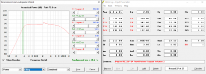
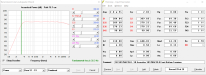
This enclosure seems to work well with a wide variety of drivers - on the Facebook TL group, a fellow asked about using a 6 1/2" SB Acoustics aluminum woofer (that has na impressively low Fs of 31.5Hz) and with only a narrowing of the L45 segement, it has the flattest response I have ever seen (in my very limited time working with Hornresp).
I am going to see if it can be made smaller - but the proportions of this design seem to pretty darn flexible.
I am going to see if it can be made smaller - but the proportions of this design seem to pretty darn flexible.
Attachments
Maybe take a look at this too.
https://www.diyaudio.com/forums/sub...ission-line-simulation-model.html#post6481928
https://www.diyaudio.com/forums/sub...ission-line-simulation-model.html#post6481928
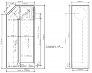
For the SB Acoustics 6.5" aluminum woofer, I slimmed the enclosure down a bit, and added space for a dome tweeter. It *still* has a remarkably smooth response in the Hornresp model.
Attachments
I picked up 2 sheets of 18mm x 5' x 5' Baltic birch plywood this afternoon, and I will be taking them to a friend's professional woodshop tomorrow! So, I may be able to post pictures of progress, soon.
I'll need to get binding posts and internal wires, sooner rather than later.
I'll need to get binding posts and internal wires, sooner rather than later.
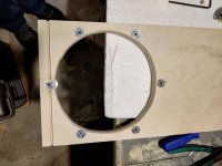
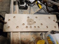
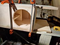
We got the panels cut yesterday, and today I cut the woofer holes, set up the T-nuts, and cut the openings in the braces. Tomorrow gluing begins!
I will need to test whether or not the tweeter needs side baffles - I will not cut the 45 degree slope on the side panels and measure the tweeter with an without side and top baffles.
I will need to test whether or not the tweeter needs side baffles - I will not cut the 45 degree slope on the side panels and measure the tweeter with an without side and top baffles.
Attachments
Last edited:
I'd be curious to know the difference in frequency response between that enclosure and the EXACT same enclosure without the middle panel. Even though I know it's a Transmission Line, I still SEE bass reflex. Mount the driver on the middle panel and I see the performance going up...lower distortion, maybe lower cutoff, and probably more power handling.
We got the panels cut yesterday
To late to suggest that you extend the brace to at least the top and brace the back of the bass driver to the top and back of the box.
dave
Yes, though earlier on I did consider this. The 3 edges of the front baffle are very close the sides and top, with the top T-nut actually buried in the joint between the front baffle and the top, and the brace is a inch away from the sixth bolt on the bottom of the woofer, so the structure is quite robust.
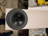
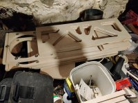
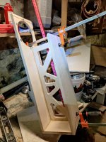
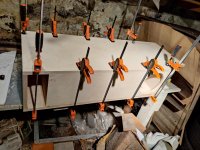
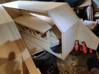
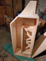
Here's the front baffle and the brace and the internal baffles - I glued up both sets today.
Here's the front baffle and the brace and the internal baffles - I glued up both sets today.
Attachments
I'd be curious to know the difference in frequency response between that enclosure and the EXACT same enclosure without the middle panel. Even though I know it's a Transmission Line, I still SEE bass reflex. Mount the driver on the middle panel and I see the performance going up...lower distortion, maybe lower cutoff, and probably more power handling.
I am eager to hear how this comes out. I think the bass quality of a TL is better than other enclosure types - they have the "speed" of open baffle and better extension than ported.
I'd be curious to know the difference in frequency response between that enclosure and the EXACT same enclosure without the middle panel.
Basically, for a given MLTL alignment the 1/4 WL TL action allows a larger and/or shorter vent, which of course in turn allows greater output/driver damping around/at Fb and since the trade-off is a larger cab [Vb], its BR equivalent will either be under-damped and/or need to be tuned lower, so either way more pass band 'ripple', hence more stuffing/loss of acoustic efficiency.
Being an 'acoustic solutions for acoustic problems' type, personally don't see any of this as better performance per se, but as always YMMV.
")
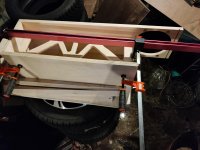
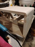
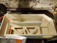
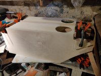
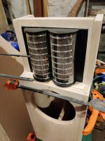
I have been working on these cabinets, and today I finished the "notch" on the sides of the tweeter, and I then have glued one side to the 8 "middle" pieces on one cabinet. The other side is there for clamping purposes - I will glue it on next, so it can be on the bottom, so the glue stays in place.
Attachments
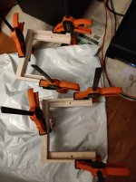
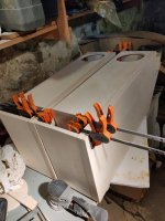
Thanks! It is good to be building something. Today I glued the side on the second speaker, and I cut and sanded the tweeter frames. I used a jigsaw and a random orbital sander to clean up the cuts, and get them to fit.
Attachments
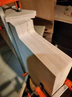
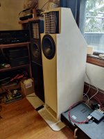
I measured the tweeter response, and it is very similar with and without a baffle. So I decided to modify my design, and gave the sides a gentle arc, to make the top a little wider. Which will look better, I think. I have been doing a lot of sanding.
Attachments

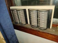
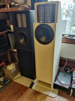
I have one of the speakers assembled and the second is getting close! I have not done a sweep yet, so I can make the driver EQ filters; but I will do that soon. So far, with the setup from the LT1000, it sounds very good.
I used a scale to get 200 grams of poly fill, for each, and the wires are supporting the majority of it up behind the woofer.
I used a scale to get 200 grams of poly fill, for each, and the wires are supporting the majority of it up behind the woofer.
Attachments
Last edited:
- Home
- Loudspeakers
- Full Range
- An Improved Transmission Line Alignment