I wouldn't call it issues, in fact, it is why I signed up for arrays. Even though it may seem to be a small window, if you consider where the floor and ceiling are you'll see that it plays less of a role in listening to these while maintaining plenty of room to move around while keeping an undisturbed output.
Comparison of a single TC9 array vs an array:

Again, watch the orange 'in-room' prediction. The array barely has a change in output while a single driver's FR goes berserk once we introduce the floor and ceiling reflection. So I'd definitely say the Array has the advantage here. At least in what I'm trying to accomplish.
(aside from the obvious gain in level and dynamics)
Comparison of a single TC9 array vs an array:
Again, watch the orange 'in-room' prediction. The array barely has a change in output while a single driver's FR goes berserk once we introduce the floor and ceiling reflection. So I'd definitely say the Array has the advantage here. At least in what I'm trying to accomplish.
(aside from the obvious gain in level and dynamics)
Attachments
Last edited:
Definately better on paper.
That’s the reason I’m building mtm’s but I’m not ‘allowed’ to work on them until I finish the kitchen cabinets! Sanding doors today and finishing mon/tues hanging them weds/thurs so might actually be building speakers by next wknd......I’ve had all the parts for almost a year now!
That’s the reason I’m building mtm’s but I’m not ‘allowed’ to work on them until I finish the kitchen cabinets! Sanding doors today and finishing mon/tues hanging them weds/thurs so might actually be building speakers by next wknd......I’ve had all the parts for almost a year now!
Board 5 and 6 are ready...
Again a small deviation in the resistance value, the sim is with 58 Ohm (instead of 60).

This will be it for a while, have to wait for parts to arrive before I can continue.
However next week the work on our living room starts so I'll have to wait and see when I can pick up the pace again. All in all I'm happy with the work so far, this should work as advertised") .
.
Again a small deviation in the resistance value, the sim is with 58 Ohm (instead of 60).
This will be it for a while, have to wait for parts to arrive before I can continue.
However next week the work on our living room starts so I'll have to wait and see when I can pick up the pace again. All in all I'm happy with the work so far, this should work as advertised
.Attachments
I can hardly wait (but will have to ) to see what this tweak will bring in real life. Its main purpose is to get the results even less reacting to floor and ceiling, softening the effects of the room even further.
I've looked at off axis angles and compared those sims to unshaded and it really should be more than just a marginal change at different heights and off axis angles.
Most probably it will also mean the mid/side tweaks will become even more important, as the room will not be assisting as much to hide those cross talk dips and peaks. That's something we can already see in the comparison between a single TC9 vs the array.
The floor/ceiling reflections, like with the single driver, will help hiding this cross talk, while making a speaker react less to floor and ceiling reflections will uncover this phenomenon more. If that is a good thing or not? I cannot predict that yet, which makes this an experiment at best.
So far, the mid/side EQ and ambient channels have been the most successful experiments I've done, that's why I'm hoping this tweak will bring this to an even higher level. It isn't easy to predict what will happen, so I won't go there. But it has been a valuable lesson to see what makes an array tick in a room, why it is more obvious/easy to hear changes in cross talk etc. compared to more regular speakers.
The question will remain if that actually is a step forward or not.
) to see what this tweak will bring in real life. Its main purpose is to get the results even less reacting to floor and ceiling, softening the effects of the room even further. I've looked at off axis angles and compared those sims to unshaded and it really should be more than just a marginal change at different heights and off axis angles.
Most probably it will also mean the mid/side tweaks will become even more important, as the room will not be assisting as much to hide those cross talk dips and peaks. That's something we can already see in the comparison between a single TC9 vs the array.
The floor/ceiling reflections, like with the single driver, will help hiding this cross talk, while making a speaker react less to floor and ceiling reflections will uncover this phenomenon more. If that is a good thing or not? I cannot predict that yet, which makes this an experiment at best.
So far, the mid/side EQ and ambient channels have been the most successful experiments I've done, that's why I'm hoping this tweak will bring this to an even higher level. It isn't easy to predict what will happen, so I won't go there. But it has been a valuable lesson to see what makes an array tick in a room, why it is more obvious/easy to hear changes in cross talk etc. compared to more regular speakers.
The question will remain if that actually is a step forward or not.
Last edited:
Board 5 and 6 are ready...
Again a small deviation in the resistance value, the sim is with 58 Ohm (instead of 60).
This will be it for a while, have to wait for parts to arrive before I can continue.
However next week the work on our living room starts so I'll have to wait and see when I can pick up the pace again. All in all I'm happy with the work so far, this should work as advertised
Wesayso: question: the directivity plots you show are wrt the angle to the center of the array? Or ear height? Also I would assume these plots are very distance dependant? So at what distance is this simulated? I have 2 meter high line arrays (electrostatics) and did not see such extreme vertical beaming...
Quite honestly I did not expect to see this much vertical 'beaming' either, based on my experience out in the room with arrays.
But if I figure that standing up, at the same distance as these plots are simulated at, would move me towards about a 14 degree angle off axis vertically(*), I do believe the sim is pretty much capturing what really happens.
(*)= off axis at ~14 degree from the design (ear) height.
The sim is displaying the results at ear height, where I've EQ-ed the (chosen) listening window. In real life I would measure in room and EQ that part. Either with an average of multiple measurements or single point and soften the overcorrection of the DSP results due to using that single position. If you look at the correction curves of the straight array without shading and the one with frequency shading you see the shaded array has way less dips and peaks in it's correction. That's a sign for me that EQ based on a shaded array is going to work over a wider area.
I started joining the sims that nc535 did because there was quite a bit of familiarity to my in-room measurements in the sims he did. Especially when factoring in the floor and ceiling reflections, or prior to that, a mirror floor image that Jack had simulated.
These simulations were done at ear height, at about 2.7 meter. I've tried to model everything as close to what I use out in the room. Still looking for trends though, not relying on the absolute outcome these sims are predicting. The real in room results will have to tell that story.
An electrostatic has a seamless membrane from which the sound is generated, in that way it won't suffer from ceiling splash like we see in these array predictions. That ceiling splash or lobing has to do with driver spacing.
But the results of these sims were as much a surprise to me as they seem to be for you.
Last edited:
If we look at the listening height, and use that point to EQ, with the unshaded array we should have a point of symmetry above it, with an equal amount of drivers above and below. Differing only in the way they react with the room, because the distance to ceiling is different than distance to floor (at least in my case).
So let's look at it in graphs, first the unshaded array at listening (and EQ) height:
So, about 342 mm higher the predicted result should be the same...

(and it is...)
The (predicted) in-room result will differ, because those distances did change.
All in all it may seem like a narrow vertical band, but in actual results it will be pretty even from a very low height until about standing height.
My proposed tweak moves the non-shaded center drivers towards the listening height (at 1 meter), and the shading results in less waistbanding overall and a better behaved upper response.
However the compromise is that standing performance won't be quite ideal, but to be brutally honest, it wasn't ideal with the unshaded array either, it just had a different compromise, a different overall balance as it suffered at ~600 Hz, making it within +/- 2.5 dB over the entire frequency range.
The shaded array still stays within the same +/- 2.5 dB overall and actually is a bit flatter overall, at least in the prediction, but with more of a downwards trend over the entire bandwidth.
That's the compromise I'm willing to make, if the overall seated performance is indeed perceived as better than before.
The vertical window for the shaded array from about 30 cm to ~1800 cm will still be within about +/- 2.5 dB at a listening distance of 2.7 meter. (due to the shading chosen) That's actually a bit better than the unshaded array could accomplish. Real life will have to tell us if these predictions are on the mark.
So let's look at it in graphs, first the unshaded array at listening (and EQ) height:
So, about 342 mm higher the predicted result should be the same...
(and it is...)
The (predicted) in-room result will differ, because those distances did change.
All in all it may seem like a narrow vertical band, but in actual results it will be pretty even from a very low height until about standing height.
My proposed tweak moves the non-shaded center drivers towards the listening height (at 1 meter), and the shading results in less waistbanding overall and a better behaved upper response.
However the compromise is that standing performance won't be quite ideal, but to be brutally honest, it wasn't ideal with the unshaded array either, it just had a different compromise, a different overall balance as it suffered at ~600 Hz, making it within +/- 2.5 dB over the entire frequency range.
The shaded array still stays within the same +/- 2.5 dB overall and actually is a bit flatter overall, at least in the prediction, but with more of a downwards trend over the entire bandwidth.
That's the compromise I'm willing to make, if the overall seated performance is indeed perceived as better than before.
The vertical window for the shaded array from about 30 cm to ~1800 cm will still be within about +/- 2.5 dB at a listening distance of 2.7 meter. (due to the shading chosen) That's actually a bit better than the unshaded array could accomplish. Real life will have to tell us if these predictions are on the mark.
Attachments

Because you or someone else recently posted in this thread, I just now found it. Amazing that it's been almost seven years in the making!
That's surprising, since limited vertical dispersion is a hallmark trait of line arrays. Line arrays have traditionally been used in situations where one wants a wide horizontal dispersion and narrow vertical dispersion. This is well-understood and documented in the loudspeaker acoustics literature since at least the 1950s. I used a line array in a commercial installation way back in about 1980 for that exact reason. You will see that many (most) auditorium and large-scale sound systems for concerts today use line arrays for the same reason."I did not expect to see this much vertical 'beaming'"
Well Dave, that's not quite what I meant with those words. Of course I knew about the directivity or I would't even have build myself a pair. However I had never seen it in simulation like Vituixcad provides.
Where it seems like a small narrow beam, as a prediction like that goes 360 degree and does not translate that easy to a real room with a floor and ceiling.
In other words, I don't expect a 2M tall electrostatic like the one from mvs0 to look very different, except for the lobing I have in my plots with my multiple drivers. But seeing it in a plot like this requires some adjustment.
In other words, seeing how this directivity looks in a plot like that was new to me. But I had studied arrays well before building myself a pair, don't you worry. That exact behaviour made me want them in the first place.
The sims I had seen from arrays like Roger Russel's IDS and the samples from Don Keele etc, left a lot to figure out. They were done or at least presented in an entirely different way. Seeing it in a plot like this took some getting used to, to figure out what I was seeing, that's all.
Yes, this thread has been going for that many years, but the setup has been blasting music (satisfactory I might add) for the better part of those years. I just treat it as an experimental setup to learn from. As my personal lab... I try and keep coming up with ways to improve my results instead of building myself new speakers ever so often. This has worked out quite well.
Because of the array's nature, they act different than most any other speaker inside a room. It is the reason I opted for them. But if I had a big spare room without boundaries I might have gone with a (big) Horn setup.
Anything that could improve direct vs indirect sound so I can control the results that much better. (like with my ambient speakers and mid/side EQ)
Where it seems like a small narrow beam, as a prediction like that goes 360 degree and does not translate that easy to a real room with a floor and ceiling.
In other words, I don't expect a 2M tall electrostatic like the one from mvs0 to look very different, except for the lobing I have in my plots with my multiple drivers. But seeing it in a plot like this requires some adjustment.
In other words, seeing how this directivity looks in a plot like that was new to me. But I had studied arrays well before building myself a pair, don't you worry.
That exact behaviour made me want them in the first place.The sims I had seen from arrays like Roger Russel's IDS and the samples from Don Keele etc, left a lot to figure out. They were done or at least presented in an entirely different way. Seeing it in a plot like this took some getting used to, to figure out what I was seeing, that's all.
Yes, this thread has been going for that many years, but the setup has been blasting music (satisfactory I might add) for the better part of those years. I just treat it as an experimental setup to learn from. As my personal lab... I try and keep coming up with ways to improve my results instead of building myself new speakers ever so often. This has worked out quite well.
Because of the array's nature, they act different than most any other speaker inside a room. It is the reason I opted for them. But if I had a big spare room without boundaries I might have gone with a (big) Horn setup.
Anything that could improve direct vs indirect sound so I can control the results that much better. (like with my ambient speakers and mid/side EQ)
Last edited:
Quite honestly I did not expect to see this much vertical 'beaming' either, based on my experience out in the room with arrays.
But if I figure that standing up, at the same distance as these plots are simulated at, would move me towards about a 14 degree angle off axis vertically
Now I only realise that with small angles you cover already quite some height range given the height of the array and listening distance.
In my case (h=200cm and d=340cm) an 14 degree angle would cover a height range of 100cm +/- 82cm , so from 18cm to 182cm.
(I would not call that 'narrow'
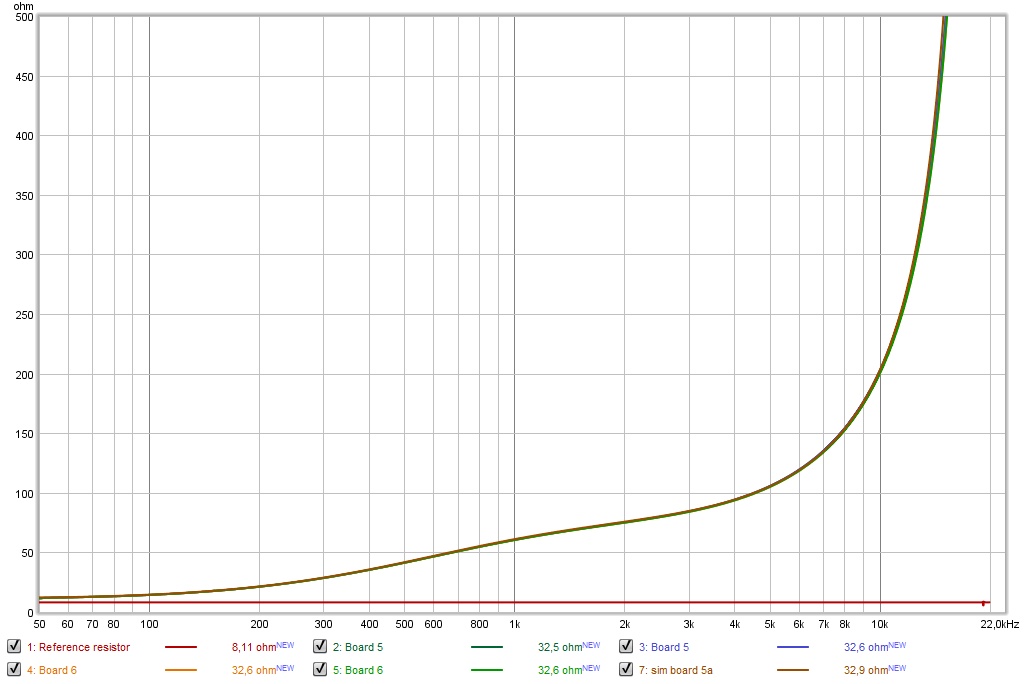
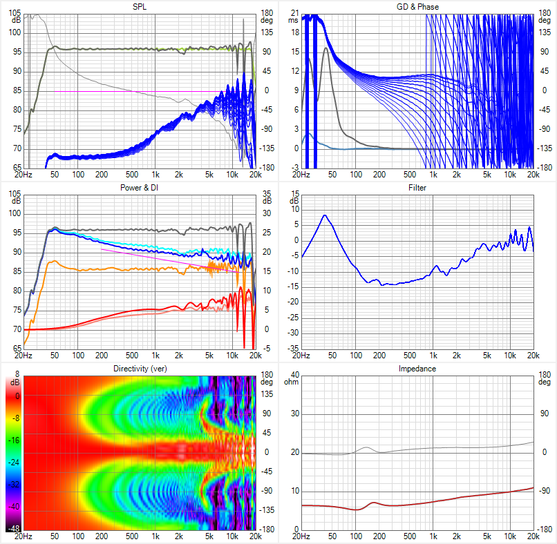
)The remaining parts came in, here's a plot of the first of final 2 boards, compared to its sim:
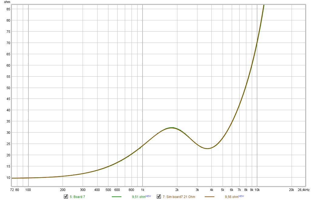
The sim is with 21 Ohm resistance instead of 22 Ohm, just like the previous boards a small deviation there, to get the simmed plots very close to the measured result. Hoping the second one will turn out similar.
Sadly, the ClarityCap SA series were on backorder, so I suggested and received a replacement for both 0.33 uF caps, the Audyn MKP Plus. That line of caps is quite a bit larger, as it consists of two separate polypropylene foil connected in series, bi-filar. The build quality is excellent compared to the ClarityCap SA series. I measured the caps by themselves to possibly mix and match. The ClarityCaps showed a small difference in value between the two 2.7 uF caps, the Audyn's were both measuring exactly the same. Values were lower so it's easier to be the same, but tolerances are higher too for the MKP Plus.
I had to re-arrange my planned board layout to make it all fit though. I'll show pictures later on when I finish the last board. I still have to solder that one.
Attachments
Last edited:
I have 2 meter high line arrays (electrostatics) and did not see such extreme vertical beaming...
Quite honestly I did not expect to see this much vertical 'beaming' either, based on my experience out in the room with arrays.
I have a feeling that the full 360 degree view of the polar plot shown in Vituix makes it seem worse than if it was displayed -90 to +90 like the majority of polar plots are.
Even though the data will be the same the presentation might appear different.
The effects of directivity like that are clearly visible though:
Looking at the orange in-room result of an array vs single driver and the effects of floor and ceiling on the output (orange in-room prediction).
While horizontal results stay similar to that of a single driver. Makes me curious about using a Tekton tweeter array on the top end. Some day I will sim that out of curiosity.
It keeps the top end array, it would share the load on many drivers and might solve that last bit of lobing? But... and it's a big but... it would need a crossover.
Looking at the orange in-room result of an array vs single driver and the effects of floor and ceiling on the output (orange in-room prediction).
While horizontal results stay similar to that of a single driver. Makes me curious about using a Tekton tweeter array on the top end
. Some day I will sim that out of curiosity.It keeps the top end array, it would share the load on many drivers and might solve that last bit of lobing? But... and it's a big but... it would need a crossover.
Attachments
Last edited:
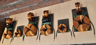
As promised, a picture of the last board(s):
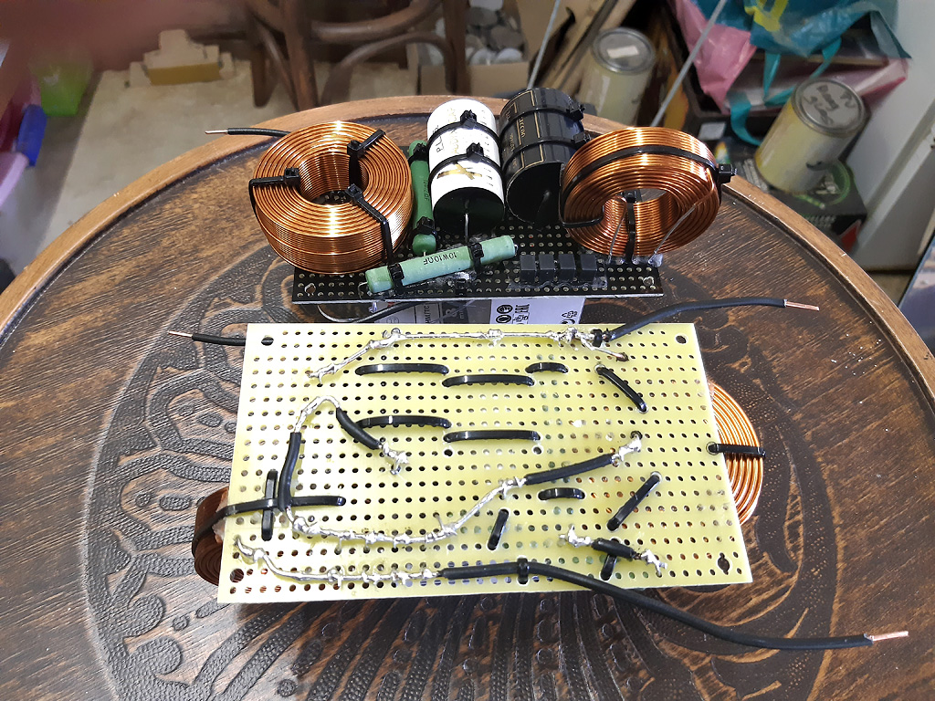
I flipped one upside down for those who are making notes (lol).
See how the 0.33 uF cap from Audyn (MKP Plus) is almost as large as the ClarityCap SA 2.7 uF? It's longer already!
In front of those two there is a Vishay MKP1837 0.01 uF. You can see it in the solder traces how it's hooked up.
I flipped one upside down for those who are making notes (lol).
See how the 0.33 uF cap from Audyn (MKP Plus) is almost as large as the ClarityCap SA 2.7 uF? It's longer already!
In front of those two there is a Vishay MKP1837 0.01 uF. You can see it in the solder traces how it's hooked up.
Attachments

Last edited:
.... keeps the top end array, it would share the load on many drivers and might solve that last bit of lobing? But... and it's a big but... it would need a crossover.
You could go digital.
Your whole setup is anyway. So, I doubt that would be the hard part.
So I just did a quick sim of flanking the central 8 drivers of a line array flanked by columns of 8 low pass filtered drivers and tuned the amplitude, delay, and low pass cut off for the best horizontal response. This is kind of Tektonish.
I was able to narrow the horizontal response from 500 Hz up to where it met up with natural narrowing due to driver beaming at HF. Not perfectly uniform horizontal but really reduced the front and sidewall reflections. Just a start at this kind of thing. It would be simple to sim the original Tekton array in Vituix but I left that for later.
You could get this narrowing also going OB but then you loss bass. This way the additional drivers add bass response. Good to use a driver like TC9 that isn't too expensive...
And worry about getting yet another amp to power that
The madness never ends...
In all fairness, I don't yet see what I want to see in Stereophile's test of a Tekton. As said, I'll probably sim it at some point in the future. No hurry, but interesting nonetheless.
You would need an array of amps. I have a 4x140W Pascal module based amp on order from VTV Amplifiers but I have also been looking into amplifier architecture for something suitable for lots of low power channels with good fidelity. The answer seems to be a composite amplifier using error correction to drive the nonlinear distortions down an order of magnitude below what you get without the global feed back loop. Best example is Neurochrome 186 which uses LM3886 chip amp plus several op amps - but its priced a little high. In the headphone amplifier forum there are people looking at multiple op amps in parallel - up to 32 - to get a simple, low cost design with very low distortion. Now if we could get someone with actual amplifier design DIY experience to develop something to suit this application...
- Home
- Loudspeakers
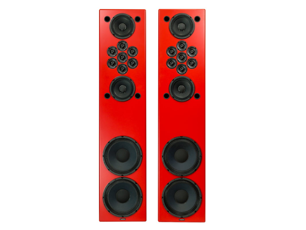
- Full Range
- The making of: The Two Towers (a 25 driver Full Range line array)