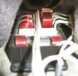
I was looking for something to put between the coils and the phenolic board to possibly reduce vibrations to excite the board/coil if they are stuck together rigidly. Maybe this applies to capacitors as well. As they are known to be able to sing too  .
.
After looking up the specs for double sided tape, even a high temperature variant, I did not find anything useful. A max temperature resistance of 150 degree (short term) was the best i could find.
Then it struck me that wool is known to be a good fire retardant. So should I stick a small patch under the coils/capacitors (not resistors) to have them avoid to resonate the boards? Still locking them down with zip ties.
For instance, Von Schweikert has it's entire crossover potted:

... to avoid vibrations.
.After looking up the specs for double sided tape, even a high temperature variant, I did not find anything useful. A max temperature resistance of 150 degree (short term) was the best i could find.
Then it struck me that wool is known to be a good fire retardant. So should I stick a small patch under the coils/capacitors (not resistors) to have them avoid to resonate the boards? Still locking them down with zip ties.
For instance, Von Schweikert has it's entire crossover potted:
... to avoid vibrations.
Attachments
Last edited:
Maybe just stick with a double sided tape: Sonic Barrier Damping Material For SDA SRS 1.2TL Crossover — Polk Audio
There is always someone who has tried it, it seems...
There is always someone who has tried it, it seems...
B&W diamond head crossovers, glued and tightened with cable ties...

Troels: glued... (with something much like Polymax) Tips and ideas Copyright 2012-14
Troels: glued... (with something much like Polymax) Tips and ideas Copyright 2012-14
Attachments
Last edited:
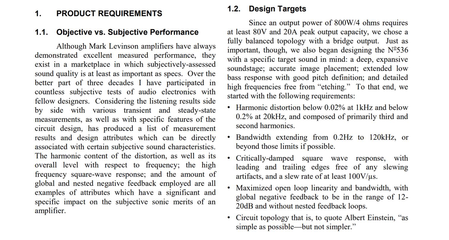
This is a screenshot of the intro to an AES paper "New Design Methodologies in Mark Levinson Amps" I thought it would be interesting given past conversations here about amplifier sound quality. The author claims to know what is needed for exceptional sound quality and the design targets for achieving them are daunting.
Attachments
Ran into a little snag... my order of caps and coils had a few errors. I'm missing two coils and had one erroneous cap value delivered to me.
I hope it will be resolved soon.
I started on the first board and fitted the components. Still have to do the wiring.
Cutting the boards to size was a breeze with the Dremel tool. (Thanks fluid)
I hope it will be resolved soon.
I started on the first board and fitted the components. Still have to do the wiring.
Cutting the boards to size was a breeze with the Dremel tool. (Thanks fluid)
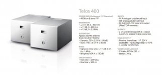
Have you read the rest of that paper too, nc535? I'd say Goldmund has a lot of those targets/boxes nailed/ticked with its very wide bandwidth, low enough distortion, good square wave performance, a slew rate above 200V/us...
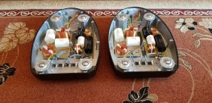
A relatively simple and optimised topology that has been shaved into whatever their target was over decades of fine tuning. Not stating my clone has all those merits but I think it might be quite close but it is missing the elaborate power supply featuring 4 toroidal transformers. I have only one (big one) per channel.

A relatively simple and optimised topology that has been shaved into whatever their target was over decades of fine tuning. Not stating my clone has all those merits but I think it might be quite close but it is missing the elaborate power supply featuring 4 toroidal transformers. I have only one (big one) per channel.
Attachments
Its so hard to get the BOM exactly right!
It seems like it, on paper everything was fine
.An impression of the first board:
(so something is happening at last...)
Last edited:
Originally I was opting for a bypass cap for the ClarityCaps, as I did order more Vishay MKP1837's than I needed. But after reading many threads on bypass caps in general I decided to leave it as is. I think I may have been reading too much Cap reviews and got into that "groove". You know, the rating cap kind.
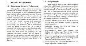
As is, these bigger caps are there to lift the energy back up again around 4-5 KHz to be able to balance the "standing" performance. The row of Vishay caps on the right are responsible for a quicker decline than a coil by itself above 10KHz (using them as a notch that centers around ~20 KHz).
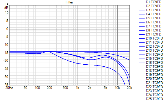
As all caps are sort of bypassing the coil or coil/resistor I guess it doesn't even make sense to think about using bypass caps like the Vishay 0.01 uF. On a tweeter or mid? Who knows if it ever makes sense at all... I certainly wouldn't know.
From a pure technical or scientific standpoint there seems to be very little evidence pointing in that direction. At least none that I could find.
As is, these bigger caps are there to lift the energy back up again around 4-5 KHz to be able to balance the "standing" performance. The row of Vishay caps on the right are responsible for a quicker decline than a coil by itself above 10KHz (using them as a notch that centers around ~20 KHz).
As all caps are sort of bypassing the coil or coil/resistor I guess it doesn't even make sense to think about using bypass caps like the Vishay 0.01 uF. On a tweeter or mid? Who knows if it ever makes sense at all... I certainly wouldn't know.
From a pure technical or scientific standpoint there seems to be very little evidence pointing in that direction. At least none that I could find.
Attachments
Last edited:
Just subjective but fwiw I notice a difference with a bypass cap on the tweeter, it supposedly works best with larger/longer caps and I tend to concur with that. I’ve tried many different brands/types and the cheapest one impressed me the most (Cornell dubilier 940c) swapping between 0.10 and 0.01 the latter taking the lead in my case. Seems to add clarity to the airiness and timing is more on the money.
Edit....I’ve also used clarity cap csa’s (on mids in my case) and find them to be quite agreeable.
Edit....I’ve also used clarity cap csa’s (on mids in my case) and find them to be quite agreeable.
Last edited:
Thanks Bob, I've read more reports like that and I know the Vishay's I got for the top end were quite popular in that specific bypass function.
(and they cost next to nothing too)
However, I did read a lot of contradictory information as well, and as this isn't a bypass on a high-passed mid or tweeter, as the caps functions differently in my circuit, I left it out.
After all, I still have 5 drivers playing full range without any passive components in their path.
I can't rule out the possibility that it works though. Even though I'm a measurement guy, as this thread has shown, I've had my share of: why does this sound (that much) better? I've heard differences in wires, usually cause for another long debate. But I could measure differences too!
Our joint amplifier test with koldby BYRTT and myself would also fall into that category. I did not expect that much differences between the tested amplifiers. So I'm as open for things like this as I can be, without being willing enough to slide down the slippery slope.
Relatively though, the ClarityCap values I use are small, 1.5 uF and 3 uF in my circuits, and the Vishay caps follow it in the next step of the circuit.
I've seen it stated that a large cap + bypass cap functions more linear than a single cap of similar/same value. But that's what it was, a statement.
If I insert these circuits and close up again I'm not going to re-open the arrays to either insert or remove a bypass cap. It's just too much work.
But if more people, like koldby, nc535, fluid or BYRTT tell me it would be a good idea to use a o.o1 uF bypass on the ClarityCaps, in they go.
(and they cost next to nothing too)
However, I did read a lot of contradictory information as well, and as this isn't a bypass on a high-passed mid or tweeter, as the caps functions differently in my circuit, I left it out.
After all, I still have 5 drivers playing full range without any passive components in their path.
I can't rule out the possibility that it works though. Even though I'm a measurement guy, as this thread has shown, I've had my share of: why does this sound (that much) better? I've heard differences in wires, usually cause for another long debate. But I could measure differences too!
Our joint amplifier test with koldby BYRTT and myself would also fall into that category. I did not expect that much differences between the tested amplifiers. So I'm as open for things like this as I can be, without being willing enough to slide down the slippery slope
.Relatively though, the ClarityCap values I use are small, 1.5 uF and 3 uF in my circuits, and the Vishay caps follow it in the next step of the circuit.
I've seen it stated that a large cap + bypass cap functions more linear than a single cap of similar/same value. But that's what it was, a statement.
If I insert these circuits and close up again I'm not going to re-open the arrays to either insert or remove a bypass cap. It's just too much work.
But if more people, like koldby, nc535, fluid or BYRTT tell me it would be a good idea to use a o.o1 uF bypass on the ClarityCaps, in they go.
Last edited:
Back in the day when I actually did board designs it was not uncommon to parallel a particularly large value cap with a much smaller one to make sure that capacitor remained a capacitor over the entire frequency range that mattered. That is especially true at RF and for power supply decoupling. Its hard to imagine those effects being significant at audio - but that is my lack of any recent analog design experience speaking. I wish these caps were better specified but the specs we really need for this question have been replaced by marketing hype.
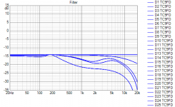
it wouldn't be hard to measure your shading filter frequency response with REW. Replace the mic with a hardwired connection to sound card line input through a resistor divider... It would be nice to know they work before opening up the arrays and that would tell you if your caps needed help.
it wouldn't be hard to measure your shading filter frequency response with REW. Replace the mic with a hardwired connection to sound card line input through a resistor divider... It would be nice to know they work before opening up the arrays and that would tell you if your caps needed help.
Have you read the rest of that paper too, nc535? I'd say Goldmund has a lot of those targets/boxes nailed/ticked with its very wide bandwidth, low enough distortion, good square wave performance, a slew rate above 200V/us...
A relatively simple and optimised topology that has been shaved into whatever their target was over decades of fine tuning. Not stating my clone has all those merits but I think it might be quite close but it is missing the elaborate power supply featuring 4 toroidal transformers. I have only one (big one) per channel.
I did but the circuit design details were over my head. One thing I did gather is they did their best to keep the circuits linear to minimize the need for feedback. They controlled the gain and the level of feedback precisely, as if they believed that the their target feedback level was critical to achieving good subjective performance.
My interest is in amplifiers suited for actively shaded arrays. How do you scale down a MarkL or Goldmund amp to 10W? My tentative answer is a chip amp plus an op amp or two with global feedback to correct the "error" (distortions) of the chip amp. Neurochrome does this with their high end LM3886 boards. The paper I quoted warns me not to count on that feedback error correction too much.
Back in the day when I actually did board designs it was not uncommon to parallel a particularly large value cap with a much smaller one to make sure that capacitor remained a capacitor over the entire frequency range that mattered. That is especially true at RF and for power supply decoupling. Its hard to imagine those effects being significant at audio - but that is my lack of any recent analog design experience speaking. I wish these caps were better specified but the specs we really need for this question have been replaced by marketing hype.
it wouldn't be hard to measure your shading filter frequency response with REW. Replace the mic with a hardwired connection to sound card line input through a resistor divider... It would be nice to know they work before opening up the arrays and that would tell you if your caps needed help.
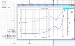
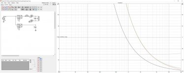
I figured I would check the impedance with REW against an X-Sim prediction like this:
That's basically what you meant right?
Attachments
I did but the circuit design details were over my head. One thing I did gather is they did their best to keep the circuits linear to minimize the need for feedback. They controlled the gain and the level of feedback precisely, as if they believed that the their target feedback level was critical to achieving good subjective performance.
My interest is in amplifiers suited for actively shaded arrays. How do you scale down a MarkL or Goldmund amp to 10W? My tentative answer is a chip amp plus an op amp or two with global feedback to correct the "error" (distortions) of the chip amp. Neurochrome does this with their high end LM3886 boards. The paper I quoted warns me not to count on that feedback error correction too much.
Reason enough for me to do the passive/active combination. That part (building amps) of this hobby is over my head anyway. Better stick to the things I can control and rely on the choices of amplification that I've made.
I'm pretty sure I have quite something with this clone done by koldby.
I don't blame you. I would go your way except for already having invested in the requisite amp channels for active (at about $225/channel). And DIYing an amp is a long shot at best, too many ways to fail or come up short. The most I would do myself is buy an amp module that I could improve, if needed, by wrapping and op amp and feedback around it. I'm finding a lot of literature about composite amplifiers and how to keep them stable. Noteworthy though is latest Topping amplifier that uses composite amplifier nested feedback topology to achieve beyond vanishing noise and distortion levels. <0.00006% THD+N, 145dB DNR
TOPPING A90 Headphone Amp – Apos Audio
I find myself compelled to understand how they did that!
TOPPING A90 Headphone Amp – Apos Audio
I find myself compelled to understand how they did that!
This is a screenshot of the intro to an AES paper "New Design Methodologies in Mark Levinson Amps" I thought it would be interesting given past conversations here about amplifier sound quality. The author claims to know what is needed for exceptional sound quality and the design targets for achieving them are daunting.
Infomercial.
That may be a valid criticism of the paragraphs I quoted but there is meat in the rest of the article.
I retrospect, I think the 200 khz -3db bandwidth target is a subtle dig at class D. Not even Purifi, gets anywhere close to that,or tries to. Perhaps this will happen when switching frequencies are extended to 2 Mhz or so. One wonders why such high bandwidth is pursued, unless the goal is to pass 20 khz squarewaves or cater to the same community that places value in tweeters whose response extends well beyond 20 khz.
I retrospect, I think the 200 khz -3db bandwidth target is a subtle dig at class D. Not even Purifi, gets anywhere close to that,or tries to. Perhaps this will happen when switching frequencies are extended to 2 Mhz or so. One wonders why such high bandwidth is pursued, unless the goal is to pass 20 khz squarewaves or cater to the same community that places value in tweeters whose response extends well beyond 20 khz.
Couple of things:I figured I would check the impedance with REW against an X-Sim prediction like this:
That's basically what you meant right?
Measuring the Z may well point out differences between the real caps and the ideal caps used in the Vituix sims. You could also measure the frequency response directly. At the high end each TC9 has about a 10 ohm Z so you might feed the LC network through a 52 ohm resistor and then run a normal frequency response sweep. XSIM will tell you what to expect. Watch the power real carefully to protect your sound card input. Doing this will tell you how close your filter comes to simulated response without "noise" from room and actual driver characteristics
You could also do a Z measurement of the capacitors themselves. I had to put what I thought were unrealistically high values of ESR, leakage R but perhaps not lead inductance in order to see a difference with ideal C.
The fact that the departure from ideal C isn't visible until high frequency implies it likely doesn't affect the frequency response significantly. The thing to check for is if the measured Z value or frequency response is a function of drive level. I have no idea if that is possible or likely but if it were the case, SQ would definitely be affected. I wouldn't do that without having a resistor pad between the filter and my sound card input.
Attachments
- Home
- Loudspeakers
- Full Range
- The making of: The Two Towers (a 25 driver Full Range line array)