Sorry did not receive any mail from you???Tried again yesterday and today (replying to an old mail), did you get anything?
Was looking through our conversations and I'm still holding my breath about your planned subwoofer towers.
I am holding mine too. Too many other projects, including DAC projects, that does not yet include more than 2 channels ;-( :
The Best DAC is no DAC
PureDSD
Signalyst DSC1
This is by far the best sound from a digital source and I dont think I can depart from that route, even though it is only 2 ch so far.
By the way, the transformer used at the output of these DAC´s would be well suited as input transformers for your SUB.
10k:10k 1+1:1+1 Permalloy Audio transformer Audio signal isolation transformer | eBay
Thanks koldby, got your reply!
Slowly but surely making some progress:
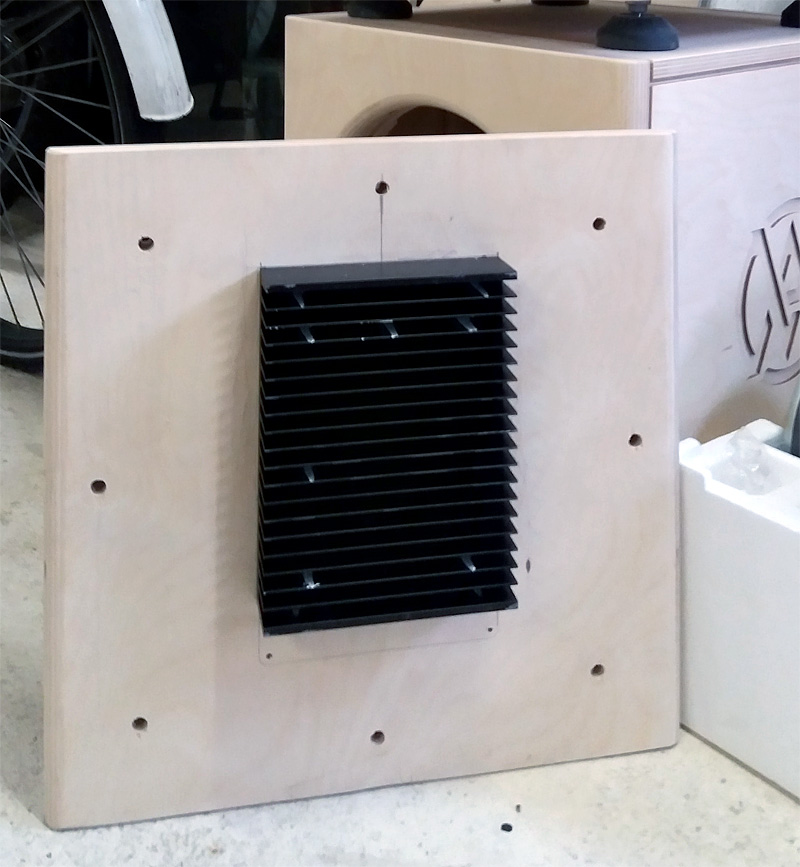
(don't worry, I will touch up the paint before I'm finished...
I did not want to tap multiple M3 holes so I went for holes between the cooling ribs)
Inner side of the panel:

Case closed:

The power cable connector, RCA and on/off switch will be mounted
beneath the heat sink. It will fit inside the inner casing. A pair of loudspeaker
cable connectors still need a place somewhere.
I'll create a left and right version to make it easy to reach the switch.
I guess I have the amplifier mounted upside down right now. It might be
preferable to have it the other way around (power supply up top). This was
just a test mount. The inner casing will be fixed and sealed and probably some
mass loaded vinyl glued on it. Heatsink will remain removable.
Slowly but surely making some progress:
(don't worry, I will touch up the paint before I'm finished...
I did not want to tap multiple M3 holes so I went for holes between the cooling ribs)
Inner side of the panel:
Case closed
:The power cable connector, RCA and on/off switch will be mounted
beneath the heat sink. It will fit inside the inner casing. A pair of loudspeaker
cable connectors still need a place somewhere.
I'll create a left and right version to make it easy to reach the switch.
I guess I have the amplifier mounted upside down right now. It might be
preferable to have it the other way around (power supply up top). This was
just a test mount. The inner casing will be fixed and sealed and probably some
mass loaded vinyl glued on it. Heatsink will remain removable.
Attachments

Thanks for the heads up, it will be possible but not easy. I think I'll run it closed first. It's easy on the bottom end to create some slits, but it would probably be more effective up top.
I browsed a lot of plate amp pictures (most of them were Class A/B though) and most of those were closed so I figured I'd be ok.
I browsed a lot of plate amp pictures (most of them were Class A/B though) and most of those were closed so I figured I'd be ok.
Hi all,
Run balanced or unbalanced...THAT is the question! ( ).
Well the need for balanced ( impedance) interconnect is real and true if:
_ you are located in a place where there is strong EMI/RFI field
_ you have long or very long run of cables ( and in this case i strongly recommend quad cables too).
In a domestic situation there is almost never a need for the second point. It is sometimes argued that balanced is beneficial and brings some benefits if the gear you use have balanced input or output.
Well in my experience it is not always true: for these benefits to be real you'll have to use gear which is FULLY differential in the signal path, which is ...rare to say the least.
Most of the time interconnect is balanced thru the use or driver/ receivers like the 1646/1246 combo for example. But the circuit is 90% of time unbalanced. So... imho there is no real need to run balanced interconnect if you keep wiring short and you are in a relatively immune spot to emi/ rfi at home.
Ground loops are a different subject but here again with a bit of thought and clean layout it can be dealt without the use of transformers and the galvanic isolation they bring.
Going pro gear for your DA may bring better quality but if you still have room to improvement with the gear you currently use here again no urge to change. That said good converters can really bring things to the table in terms of quality, at least with the generation i know ( i'm not up to date with the latter ones and how they sound, but for gear up to 5 years ago i've heard significant differences between units).
The next question is related to price/performance ratio: it's a bit like with 'audiophile' capacitors, is the price to pay in relation to the quality step up? Each one his own on this.
I bet the sub will bring things much more interesting to you for the moment. Let's finish the thing and optimise your setup Ronald! I'm waiting this for...some years now!
I have pop corn at cook and will be watching with attention the next step in your journey! And i'm not alone i think!
Run balanced or unbalanced...THAT is the question! (
).Well the need for balanced ( impedance) interconnect is real and true if:
_ you are located in a place where there is strong EMI/RFI field
_ you have long or very long run of cables ( and in this case i strongly recommend quad cables too).
In a domestic situation there is almost never a need for the second point. It is sometimes argued that balanced is beneficial and brings some benefits if the gear you use have balanced input or output.
Well in my experience it is not always true: for these benefits to be real you'll have to use gear which is FULLY differential in the signal path, which is ...rare to say the least.
Most of the time interconnect is balanced thru the use or driver/ receivers like the 1646/1246 combo for example. But the circuit is 90% of time unbalanced. So... imho there is no real need to run balanced interconnect if you keep wiring short and you are in a relatively immune spot to emi/ rfi at home.
Ground loops are a different subject but here again with a bit of thought and clean layout it can be dealt without the use of transformers and the galvanic isolation they bring.
Going pro gear for your DA may bring better quality but if you still have room to improvement with the gear you currently use here again no urge to change. That said good converters can really bring things to the table in terms of quality, at least with the generation i know ( i'm not up to date with the latter ones and how they sound, but for gear up to 5 years ago i've heard significant differences between units).
The next question is related to price/performance ratio: it's a bit like with 'audiophile' capacitors, is the price to pay in relation to the quality step up? Each one his own on this.
I bet the sub will bring things much more interesting to you for the moment. Let's finish the thing and optimise your setup Ronald! I'm waiting this for...some years now!
I have pop corn at cook and will be watching with attention the next step in your journey! And i'm not alone i think!
Last edited:
There is unlikely to be an issue with a transformer based supply and the amps themselves usually are heatsinked, the SMPS generates quite a bit of heat which can't all be taken away by the heatsink.Thanks for the heads up, it will be possible but not easy. I think I'll run it closed first. It's easy on the bottom end to create some slits, but it would probably be more effective up top.
I browsed a lot of plate amp pictures (most of them were Class A/B though) and most of those were closed so I figured I'd be ok.
At low power it shouldn't be much of an issue but the SMPS will shut down if it gets too hot. That is easier to do than you might think. Depends on how much power you will sink with the sealed box EQ.
Even a few holes top and bottom would help with natural convection.
I would run it closed first too. If vents are needed for the plate amp, the manufacturer should say so. The thing should be 90% efficient and >90% of the power should be dissipated in the switching transistors, which from the pictures are bonded to an impressive heatsink.
re' balanced vs unbalanced, not to belabor the point or preach but sharing my understanding in case someone wants to correct me
I've had to deal with hum and ground loops occasionally back in the heyday of RCA. The primary benefit of balanced for short runs would seem to be provided you ground the shield only at the driven end, that connecting the cable doesn't connect the box grounds together. You can and should do that separately paying attention to single point ground principles, as I'm sure you all know. Now that all (most) boxes use 3 wire power cords that happens naturally if they all connect back to the same electrical outlet.
When you bring that RCA input into your balanced amp, you connect the RCA shield to the "-" input of the balanced pair, and are still able to avoid connecting it to the amp ground and potentially creating a ground loop. The schematic shows an RC filter between "-" and ground. I think that is a safety thing because if grounds aren't otherwise connected a potential difference could develop between box grounds. But if you have established that common ground then you likely don't need that filter and you might gain by being able to jumper it out or switching to an RCA to XLR cable plugged into the balanced connector on the amp, if there is one.
re' balanced vs unbalanced, not to belabor the point or preach but sharing my understanding in case someone wants to correct me
I've had to deal with hum and ground loops occasionally back in the heyday of RCA. The primary benefit of balanced for short runs would seem to be provided you ground the shield only at the driven end, that connecting the cable doesn't connect the box grounds together. You can and should do that separately paying attention to single point ground principles, as I'm sure you all know. Now that all (most) boxes use 3 wire power cords that happens naturally if they all connect back to the same electrical outlet. .
Yes, this is common practice* in proworld ( studio) : when you experience hum and STILL want shielding without using a transformer that is the way to do it. However: safety first! You may read sometimes people who disconect earth to avoid hum ( often seen that from geek which doesn't understand psu issues with their computer and soundcard): never do that! You can kill yourself.
When you bring that RCA input into your balanced amp, you connect the RCA shield to the "-" input of the balanced pair, and are still able to avoid connecting it to the amp ground and potentially creating a ground loop. The schematic shows an RC filter between "-" and ground. I think that is a safety thing because if grounds aren't otherwise connected a potential difference could develop between box grounds. But if you have established that common ground then you likely don't need that filter and you might gain by being able to jumper it out or switching to an RCA to XLR cable plugged into the balanced connector on the amp, if there is one.
Well here this depend from gear. Some are known to dislike the scenario you give ( for instance my old Yamaha 02r digital mixer doesn't like this scheme at all).
The common ground ( as a starground scheme) is a must be practice if you do not want ground loops. In fact in studios we often do a dedicated 'technical ground' dedicated to audio gear to be sure... but iirc this is now forbidden to do such things and is anyway irrelevant in domestic situation.
If you want further information about all this:
Jensen Transformers Application Notes | Jensen Transformers
* usually with pro gear you have an 'earth enabling/ disabling' switch to do that. It is safer to use that than to disconnect the earth/ ground pin in a cable when there is a possibility that this cable be used with microphone: in some particular case with phantom power and poor dynamic microphone this can be dangerous as the mic is potentially exposed to 48v dc. If a musician want to have 'nude feet' it can be really dangerous too.... sorry for poor wording i hope you got the idea thoug.
Last edited:
I would run it closed first too. If vents are needed for the plate amp, the manufacturer should say so. The thing should be 90% efficient and >90% of the power should be dissipated in the switching transistors, which from the pictures are bonded to an impressive heatsink.
I don't want to labour my point either as it was intended as a head up in case a solution was easy to implement.
Wesayso is using an OEM module, when Hypex sells that as a plate amp they put it on an aluminium plate with vents top and bottom to aid convection. The amp doesn't need a huge heatsink but some airflow is a good idea.
Having built 4 amps with SMPS's from three different manufacturers the supplies all put out more heat than I thought they would, so I wanted to pass that on.
Attachments
Thanks for the heads up, it will be possible but not easy. I think I'll run it closed first. It's easy on the bottom end to create some slits, but it would probably be more effective up top.
I browsed a lot of plate amp pictures (most of them were Class A/B though) and most of those were closed so I figured I'd be ok.
Yes - but Hypex tend to run a fair bit hotter than the rest of the bunch. Make a slit below and above the plate and you get natural convection. At leasts keep good track of temp - must be some simple board on ebay etc with a display for that.
//
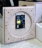
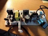
I think that all the comments about convection cooling inside the box , is based on experience with SMPS designed as the one in photo1.
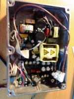
The heat producing elements in a SMPS are the switching FET´s and in the design in photo 1 they are mounted on top of the PCB with heatsinks on. Therfore they need convection cooling inside the enclosure. But , as can be seen in photo 2, the switching FET´s in the SMPS part of the Hypex module, are all bolted to the back plate (not visible on the photo, but they are. The TO220 on top of the PCB are rectifier diodes) just like the ouput FET´s in the amp section. Therefore all the heat from the SMPS as well as the amp is dissipated into the back plate and with the big heatsink Wesayso are using, there is no need for extra cooling.
I have been running the 250 W version , as shown in photo 2, with the lid on and with no other cooling (no heatsink) fullrange on my towers and they only get lukewarm after several hours.
IMHO Wesayso is on very safe grounds the way he is planning his subs.
Attachments
I appreciate all the concerns about the Hypex SMPS getting hot. I might consider putting a few extra holes in the enclosure, even though it would give me a harder time to do that on the top end.
Koldby's experience made me believe I'm save as is. I'm running a bigger heatsink on purpose. However now is the time to decide otherwise.
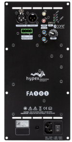
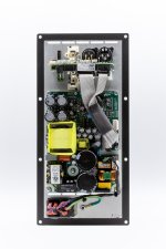
I looked up the Hypex fa501 and sure enough it is the same module as the OEM module I have and has slits for air:

(kind of surprised to see they mounted it upside down with the SMPS below the amp section, heat rises right?)
My heatsink is way bigger though than this simple aluminium plate.
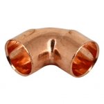
I might be able to create something simple up top with standard copper piping like these solder couplings and some copper pipe (12 mm):

The inner case is mounted lower than the outside heatsink so I need to run chimneys to get above it (lol). On the bottom end I could put in two slits between the different connectors. Those would already be sealed by the case on the inside.
It wouldn't be very hard to do, but it would be easier to just go on without based on koldby's experience. But if I have to, I'd rather do it before epoxy/paint...
Koldby's experience made me believe I'm save as is. I'm running a bigger heatsink on purpose. However now is the time to decide otherwise.
I looked up the Hypex fa501 and sure enough it is the same module as the OEM module I have and has slits for air:
(kind of surprised to see they mounted it upside down with the SMPS below the amp section, heat rises right?)
My heatsink is way bigger though than this simple aluminium plate.
I might be able to create something simple up top with standard copper piping like these solder couplings and some copper pipe (12 mm):
The inner case is mounted lower than the outside heatsink so I need to run chimneys to get above it (lol). On the bottom end I could put in two slits between the different connectors. Those would already be sealed by the case on the inside.
It wouldn't be very hard to do, but it would be easier to just go on without based on koldby's experience. But if I have to, I'd rather do it before epoxy/paint...
Attachments
Last edited:
Brilliant idea! The inner side would be sealed off with the case, while still allowing some air in between on the outside. I guess I don't even need to space out the heatsink if I just create some grooves below the heatsink that end just above it.
I want it to stay as compact as possible, but a few mm would not break anything. I'll think about both solutions while I work on the connectors.
Thanks for the suggestion! It wouldn't even have to be that much space.
Reading your reply again I guess I misinterpreted your idea, but I figure what I suggested might work and be simple enough.
The heatsink is bolted to the sub enclosure, the inner case is bolted in the inside of that same Birch Ply backplate. Easy to put a
groove on either side of the heatsink to allow for air to flow trough. Or slits below and groove up top...
Another idea is to space out the heatsink 3 mm only on the sides so it gets airflow bottom to top.
Last edited:
No problem, glad to able to helpThanks for the suggestion! It wouldn't even have to be that much space.
even if it isn't strictly necessary I thinks it's worth doing if it's simple enoughWell if I interpret this right, this is not a good idea. The heatsinks needs to have as big a surface directly coupled to the modules aluplate beneath the PCB in order to get as low thermal resistance as possible.Another idea is to space out the heatsink 3 mm only on the sides so it gets airflow bottom to top.
They still will. The modules will be bolted directly to the heatsink. The spacers will be between the heatsink and birch ply sub enclosure (but only on the sides). Leaving an air gap between the wood enclosure back plate an the heatsink. The modules will still be firmly mounted to the sink with thermal grease.
That makes sense. What will keep those vents from compromising the air seal for the woofer? The aluminum cover I see over the back of the module? That is something I wonder about. It would seem to trap residual heat inside the cover. Without it, you might not need vents. But that brings up the question of what is the ambient temperature inside the box? 9x% of the electrical power is dissipated in the voice coil as heat. Where does that heat go? (I'm sure this will be a fun discussion.)
Not going there ... I keep the inner aluminium cover as protection cover and do not worry about that one getting warm. It is indeed the cover that seals the woofer from outside air in that case. I think I'm going for that simple solution spacing out the sides of the heatsink. I'll just use 4mm mass loaded vinyl strips on each side between the enclosure and heat sink, that's easy enough.
There will be fiberglass insulation material inside the box. I'm going to stuff it somewhat to get the lowest Fs.
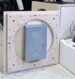
Here's the connectors on the back side:
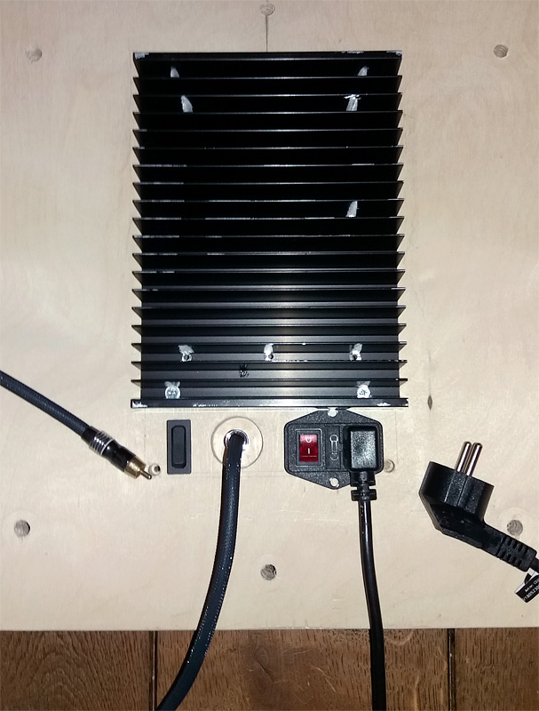
The RCA plug is somewhat sunk into the back panel to save space (15 mm). This way I can still get it close enough to the back wall, to have the front about ~ 50 cm from that wall (just like the arrays).
I still need to make a couple of ground connections, one to the inner case and one to the heatsink that run combined to the grounded power plug. I still have to find a good spot for the speaker outs on the inner case. Make some decent airflow grooves behind the heatsink on top and bottom.
But I think this is it as far as mods to the enclosure itself.
After that I just need to repeat it for the other sub.
... I keep the inner aluminium cover as protection cover and do not worry about that one getting warm. It is indeed the cover that seals the woofer from outside air in that case. I think I'm going for that simple solution spacing out the sides of the heatsink. I'll just use 4mm mass loaded vinyl strips on each side between the enclosure and heat sink, that's easy enough.There will be fiberglass insulation material inside the box. I'm going to stuff it somewhat to get the lowest Fs.
Here's the connectors on the back side:
The RCA plug is somewhat sunk into the back panel to save space (15 mm). This way I can still get it close enough to the back wall, to have the front about ~ 50 cm from that wall (just like the arrays).
I still need to make a couple of ground connections, one to the inner case and one to the heatsink that run combined to the grounded power plug. I still have to find a good spot for the speaker outs on the inner case. Make some decent airflow grooves behind the heatsink on top and bottom.
But I think this is it as far as mods to the enclosure itself.
After that I just need to repeat it for the other sub
.Attachments

- Home
- Loudspeakers
- Full Range
- The making of: The Two Towers (a 25 driver Full Range line array)